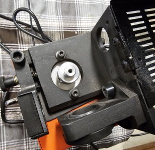
This is how I elected to limit the range of motion on the grinding seat and some of how I modeled the part (for the benefit of
@Susquatch ).
I believe the manufacturer intended to allow a rotational travel between 0 to 45 degrees. I may very well be wrong. Perhaps others can examine their grinding seat and see what they think?
I've elected to use a 5mm pin set in the tool insert as a stop.
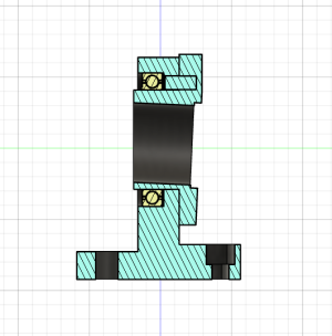
The tool insert in held in the base by the press fit bearing. Show here pressed on out of order, but you should get the gist of things.
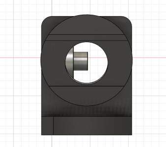
The base with milled slot to allow the 45 degrees of travel, and stop pin which is fixed into the tool insert.
I don't think the factory has a good alignment technique for press fitting the bearing, or their stop mechanism is poorly designed/made, since my grinding seat has an imperfect alignment.
I had to guesstimate a couple of criteria (by sketching a section drawing of the part) based on how and what I could measure at home without proper metrology tools other than my calipers.
I wanted to get the vertical offset angle thru the bore as precise as possible not knowing how critical this angle is. I measured the offset of the bore where it exits the protruding shaft on the bearing side. Shown circled below.
On my grinding seat I thought these were 4.5mm on top, and 2.5mm on the bottom, or a 1mm offset from center. The tricky part for me was to find out what angle that offset resulted in. I also measured the total depth of the insert from the thickest flat portion of the flange to the end of the shaft section.
I used the dimensions to lay out a section drawing similar to what is shown above. From there I extruded the solid tool insert part perpendicular to the base and the width of the full width dimensions.
Then I cut the offset angle out of a portion of the flange. The green section remains perpendicular to the base while the red section is the offset. I did this by selecting that area of the sketch and extruding a cut thru the existing part.
Then I cut out the 30mm slot thru the flange at the same angular offset as is on the face. I did this by selecting that section of the sketch and extruding it thru the part horizontally.
Only now did I have a reference to accurately draw and extrude a bore thru the tool holder. I selected the face of the cut out slot, and drew construction lines to find the center of the face. I then drew 28mm circle on the face and extruded the hole to create the bore thru the part at the correct offset angle.
Only one thing bothers me. The thinnest section of the flange at the bottom seems bigger than the actual measured part on my part. Everything else seems correct as far as I can tell.
Here is what my offset angle is... I'm thinking maybe that is 2.5 degrees in the manufacturer's design? I wont need to know for sure until I decide to make a grinding seat in ER40 size, or make more seats to use in end mill sharpener.


