• Scam Alert. Members are reminded to NOT send money to buy anything. Don't buy things remote and have it shipped - go get it yourself, pay in person, and take your equipment with you. Scammers have burned people on this forum. Urgency, secrecy, excuses, selling for friend, newish members, FUD, are RED FLAGS. A video conference call is not adequate assurance. Face to face interactions are required. Please report suspicions to the forum admins. Stay Safe - anyone can get scammed.

Tool Vevor Drill Bit Sharpener Improved

Tool
Are you going to 3D print first or go right to steel?

I assume the wheel is flipped to use the rear socket. I am usually very good at seeing things in my mind. But I haven't been able to see this one. Any orientation my mind sees doesn't work. Can you (or someone) do a Fusion model to see how that works up close and personal?

If as Ian suggests there are no flats on the shaft, and we have to flip the wheel all the time, I would want to grind flats in the shaft, or maybe there is some other approach.

I assume this is necessitated by the need to provide an adjustable Z? Could that be facilitated without flipping the wheel by a pocket and various inserts instead of a slide and inserts? Or maybe an adjustable Z slide......

Yes @Susquatch I'll test with 3D printed parts first.

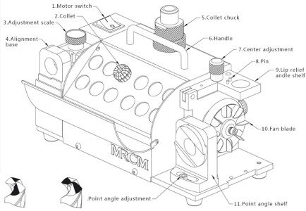
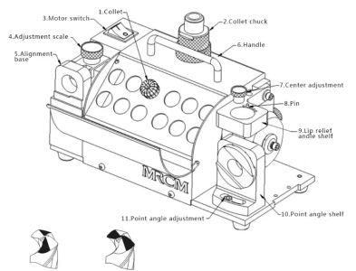
Think of my adaptation as just a variant of the standard MR-13D drill sharpener configuration with the grinding wheel in the standard orientation, widest section towards the motor mount. MRCM's nomenclature differs slightly from mine,


1736179117854.png


The tool block on the left is the web thinning, while the tool block on the right is point splitting. Not shown is the point angle grinding tool block.

You'd use this to grind all your drill bits in this configuration, there is little to adjust but it is fully adjustable. No wheel needs to be flipped or anything else as complicated as that. Just tweak the height of blocks A and B as your web diameter increases, or change the point angle to the desired setting and sharpen.

But if you wish to have an end mill sharpening session that you'd need to make further modifications to add 3 different tool blocks which copy those of the simplest design, the MR-X1 and you'd need to reverse the wheel. It is not intended as a simple process that allows user to swap between end mills and drill bits on the fly.

1736180495023.png
 

Attachments

  • 1736179358454.png
    1736179358454.png
    215.7 KB · Views: 1
  • 1736179492714.png
    1736179492714.png
    230 KB · Views: 1
As if you don't have enough to think about, take a boo at this.....


I sort of like the idea of a solid strong front frame extension for other positions. And maybe a rear/right frame too. Might be easier to do a solid frame.
 
Would adding flats affect wheel balancing or does balancing matter at all in this case???

I think it matters a lot. It was my main reason for suggesting there might be another way. I'm a bit leery of grinding or cutting two perfectly balanced flats.

Other ideas include a glued on sleeve with flats or a drilled hole for a pin.
 
As if you don't have enough to think about, take a boo at this.....


I sort of like the idea of a solid strong front frame extension for other positions. And maybe a rear/right frame too. Might be easier to do a solid frame.
This model is the MR-X3 and due to the dovetail slide for cutting the front face of the end mill I believe that the center height of the grinding wheel is higher than that of the MR-X1 and MR-13 models.

Longer term, I may just make an entirely new machine base to increase the center height of the grinding wheel so I can make the X3 model, and have evenmore options.. Easy peasy because I'd planned on making a base box to house collets and chucks etc, as well as a bottom vacuum port.
 
First attempt using the Vevor 13A.

Thanks Ian. Looks Great! Gotta be happy with that! The back grind looks perfect but I think the web on your drill is curved at the cutting edge. As a result the leading edge isn't parallel to the back grind. A better drill wouldn't do that. Doesn't matter functionally though, it should drill at least as good as your best drill.
 
First attempt using the Vevor 13A. This is a 3/8 bit originally at 118 reground to 135 split point.

View attachment 57349
The grind looks good, but in fact I spot an error.

IIRC the flats on the chuck are supposed to be parallel with your cutting edge. I think you need to review your drill setting technique and regrind this bit. Then I think it will look better and not present the anomaly that @Susquatch commented on


1736208844912.png
 
Last edited:
The grind looks good, but in fact I spot an error.

IIRC the flats on the chuck are supposed to be parallel with your cutting edge. I think you need to review your drill setting technique and regrind this bit. Then I think it will look better and not present the anomaly that @Susquatch commented on

Yes, that makes sense. One of the nuances of the drill setup procedure that is poorly documented is the need to catch the drill bit lip under the gauge ledge with the collet rotated fully clockwise. Then tighten a bit without moving, then remove and check that the lip aligns with the flats on the collet holder.

In hindsight, I agree with TB on why this happened.
Unless Ian removed the bit and then decided to return it to the chuck for a photo.
 
Unless Ian removed the bit and then decided to return it to the chuck for a photo.

Actually, I think he did. Stel and I were just chatting about that. It's too far out to work at all.

But still, the principle is the same. The grind is out just far enough to be a product of the play in the setup fixture. It is really finicky.
 
@TorontoBuilder - I really like your idea of extending the base plate and pitching the cover. This approach provides lots of optional ways to add functionality.
 
Does anyone know if that wheel nut is left handed? It's on there like my neighbour put it on with a 10ft pipe!
 
Does anyone know if that wheel nut is left handed? It's on there like my neighbour put it on with a 10ft pipe!
As per Owners Manual:

Use the left hand to hold the wheel, then use the 4mm hex wrench to loose the screw counterclockwise by right hand.
 
I got a a shipping update, seems some of my collets are due to arrive today.

Getting closer to full blown evaluation time.

I'm toying with the idea of making a full blown CAD model of the MR-13A/B/D models, and then the two lowest tier end mill cutter models if I can guesstimate the changed dimensions on the taller one

1736361586432.png
 
Back
Top