• Scam Alert. Members are reminded to NOT send money to buy anything. Don't buy things remote and have it shipped - go get it yourself, pay in person, and take your equipment with you. Scammers have burned people on this forum. Urgency, secrecy, excuses, selling for friend, newish members, FUD, are RED FLAGS. A video conference call is not adequate assurance. Face to face interactions are required. Please report suspicions to the forum admins. Stay Safe - anyone can get scammed.

Tool Vevor Drill Bit Sharpener Improved

Tool
The grinds:

Front grinding fixture cuts the end cutting edge and the axial primary relief angle with the slight concave angle by positioning the end mill at a slight angle to the vertical flat face of the grinding wheel.

1736101107635.png


The A tool plate grinds the end gash and the axial rake angle of the cutting edge by positioning the end mill against both the front of the vertical flat face and rear bevel of the grinding wheel. I believe that the positioning pins in the top of the tool insert sets the gash angle while the tilt of the plate insert sets the axial rake angle.


1736100954884.png


One of two other grinding fixtures cut the secondary axial clearance angles. The choice of which fixture to use depends on the cutter diameter.

1736101240365.png


1736101262579.png
 

Attachments

  • 1736100837414.png
    1736100837414.png
    259.9 KB · Views: 3
Hey @TorontoBuilder - something is wrong. My wheel is flat side in 45 out. Backwards to what you are showing above. It is untouched from the factory and sharpens a drill bit perfectly. Did you flip it intentionally?
 
Hey @TorontoBuilder - something is wrong. My wheel is flat side in 45 out. Backwards to what you are showing above. It is untouched from the factory and sharpens a drill bit perfectly. Did you flip it intentionally?

Nothing is wrong. There are two configurations, one for drill sharpening, with the flat towards the base upright and the 60 degree taper out towards the end.

End mill grinders are the reverse
 
Nothing is wrong. There are two configurations, one for drill sharpening, with the flat towards the base upright and the 60 degree taper out towards the end.

End mill grinders are the reverse

Awesome! I was thinking that might be the trick for something!
 
Nothing is wrong. There are two configurations, one for drill sharpening, with the flat towards the base upright and the 60 degree taper out towards the end.

End mill grinders are the reverse
So if I understand correctly to grind end mills you need to remove the grinding wheel, flip it over , and reattach it. I'd like to see every one do that.
 
So if I understand correctly to grind end mills you need to remove the grinding wheel, flip it over , and reattach it. I'd like to see every one do that.

Are you concerned about something?

But happy to do it. Prolly late tomorrow.

Hey, can you post a photo of a split point grind on your A model?
 
The manufacturer makes a bunch of machines mostly based on this design that sharpen end mills.

Recognize this machine.. two extra fixtures and a dovetail slide and voila it sharpens end mills

The reason I had asked was I thought I could see an issue in the plan. To sharpen a facet on an end mill you will need to use the flat side of the wheel or move the bit (or the wheel) in a linear motion across the across the primary relief to get a flat facet. (Each facet needs to be ground separately, The facets are not flat compared to each other.)
 
The grinds:

Front grinding fixture cuts the end cutting edge and the axial primary relief angle with the slight concave angle by positioning the end mill at a slight angle to the vertical flat face of the grinding wheel.

View attachment 57257


The A tool plate grinds the end gash and the axial rake angle of the cutting edge by positioning the end mill against both the front of the vertical flat face and rear bevel of the grinding wheel. I believe that the positioning pins in the top of the tool insert sets the gash angle while the tilt of the plate insert sets the axial rake angle.


View attachment 57256


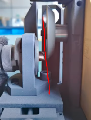
One of two other grinding fixtures cut the secondary axial clearance angles. The choice of which fixture to use depends on the cutter diameter.

View attachment 57258


View attachment 57259
Sorry just catching up on this thread. Item 8 and 9 are the important parts of the end mill sharpener. They cut the flat primary facet and the secondary (relief) facet flat. It looks like they are using the flat side of the stone to do this. (A better approach would be if you can move the bit past the wheel or move the wheel past the bit. Kind of like how a surface grinder works.)

In this configuration it would be easier to sharpen a drill bit with a 4 facet grind.
 
This video might be useful. It is 14:52 long. Describes sharpening an endmill on a D bit grinder. I know not the same tool, but gives a good description on each part of the grind process, which can then be translated to how they do it on this MRCM machine.

 
It would have been a better screw location @Susquatch , but I was trying to retain the same "insert" design to make it flexible for end mill grinding, and it did not leave enough material at that location. Here is the same parts without the insert

View attachment 57254

I may ditch that in favour of two swappable plates instead. It is just harder and more annoying to make the plates with an angled hole instead of angled insert.

As far as I can tell from all the measurements and videos and photos the A model does the point splitting using the front edge of the wheel rather than the back edge. I wasn't able to get the wheel projection on the A machines yet though to find exact projection of the A tool plate compared to the wheel

I do have the solution though. I'll put an insert type tool holder in the A tool plate location... and the normal non-insert in the B tool plate location because that is how the insert tool plate is installed on the end mill sharpener. The projection is exactly the same, because the grinding wheel is reverse with the wide flange on the outside for end mill sharoening.
Have you seen this photo from the 13D? Screenshot 2025-01-05 at 17-10-02 Mr-13d Grinding Machine 3-13mm Drill Bit Sharpener Portable ...png
 
Sorry just catching up on this thread. Item 8 and 9 are the important parts of the end mill sharpener. They cut the flat primary facet and the secondary (relief) facet flat. It looks like they are using the flat side of the stone to do this. (A better approach would be if you can move the bit past the wheel or move the wheel past the bit. Kind of like how a surface grinder works.)

In this configuration it would be easier to sharpen a drill bit with a 4 facet grind.
yes I intend to make a dovetail slide and all the tool holders for each position. The grind ends up as it should be.

Have you seen this photo from the 13D? View attachment 57289

Yes I saw a few photos of the 13D which is why I started using the 13D terminology. It is the simplest implementation but lacks vertical adjustability. It also wont work for end mill grinding in that configuration. We can do better.
 
I've tried it, I gave up! @TorontoBuilder told me the trick to doing it. I'm not sure I want to bother. Not sure if I could get it back on tight enough or to get thru the whole process without breaking something.

I tried and had difficulty too, I couldn't grip the wheel enough to resist the wrenching. Arthritis sucks. I ended up sticking a long shank allen key down from above thru the tool holder, into a grub screw on the hub to stop the wheel rotating...
 
I tried and had difficulty too, I couldn't grip the wheel enough to resist the wrenching. Arthritis sucks. I ended up sticking a long shank allen key down from above thru the tool holder, into a grub screw on the hub to stop the wheel rotating...

Isn't there a pair of flats on the axle behind the wheel for a narrow wrench? That's the normal way of doing this.

I have to go see a lawyer and pick up my mom's ashes tomorrow, but I'll take mine off later in the day if I can.
 
It is the simplest implementation but lacks vertical adjustability.
I believe there is a vertical adjustment for the split point. The holder can be adjusted to the aft and forward of the machine. This changes how deep the bit is hitting the wheel to grind the split point. (Using this method will produce a curve on the ground surface. Not a flat facet. I do not see an issue with this, but it is another reason that this will not do a true 4 facet ground drill bit.)
 
Okay this may be the final iteration before I make the parts. Independently adjustable on the Z axis.

Are you going to 3D print first or go right to steel?

I assume the wheel is flipped to use the rear socket. I am usually very good at seeing things in my mind. But I haven't been able to see this one. Any orientation my mind sees doesn't work. Can you (or someone) do a Fusion model to see how that works up close and personal?

If as Ian suggests there are no flats on the shaft, and we have to flip the wheel all the time, I would want to grind flats in the shaft, or maybe there is some other approach.

I assume this is necessitated by the need to provide an adjustable Z? Could that be facilitated without flipping the wheel by a pocket and various inserts instead of a slide and inserts? Or maybe an adjustable Z slide......
 
Back
Top