• Scam Alert. Members are reminded to NOT send money to buy anything. Don't buy things remote and have it shipped - go get it yourself, pay in person, and take your equipment with you. Scammers have burned people on this forum. Urgency, secrecy, excuses, selling for friend, newish members, FUD, are RED FLAGS. A video conference call is not adequate assurance. Face to face interactions are required. Please report suspicions to the forum admins. Stay Safe - anyone can get scammed.

Jswain's active projects

Here’s a whole slew of threads to bookmark.
Bookmarked!

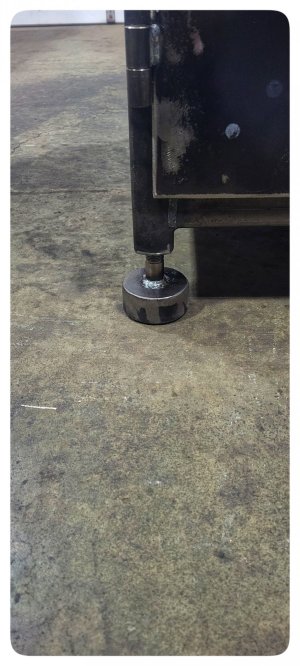
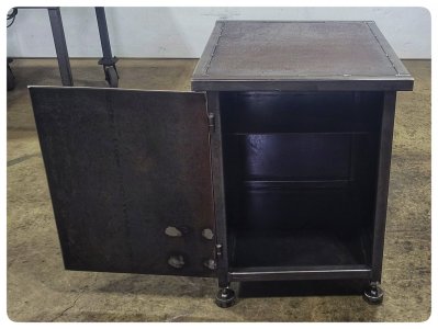
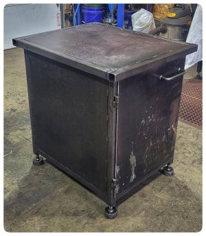
Some more success. All the levelling feet are machined just gotta cut some pads to weld onto the bottom. The threading portion went pretty good & quick. I left them slightly tight, thread in by hand but takes some effort to hopefully keep them from wobbling.
 

Attachments

  • 1000005875-01.jpeg
    1000005875-01.jpeg
    225.5 KB · Views: 8
  • 1000005876-01.jpeg
    1000005876-01.jpeg
    705.4 KB · Views: 8
I left them slightly tight, thread in by hand but takes some effort to hopefully keep them from wobbling.

It's a good intention but prolly not required. The angle on the thread faces provides a natural anti-wobble / centering force when loaded. The main source of any wobble will happen when the female part isn't long enough.

Btw, very nice work! Especially for your first shot at single point threading!
 
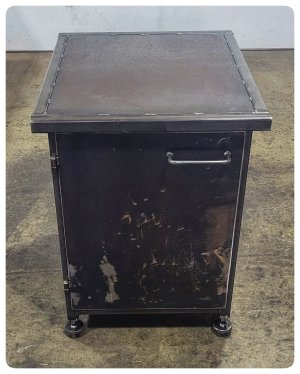
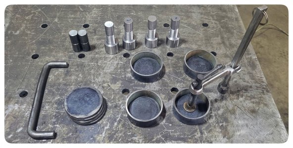
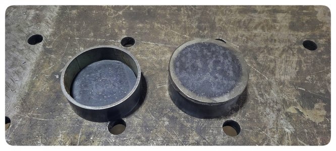
Got all the materials cut out for the feet. Settled on some ~ 2-1/2" tube that I cut out some 1/4" plates top and bottom for.

Sliced a bit of other random scrap tube for a template, then plasma cut around the OD which left me with a plate to fit inside the tube. Then i used the first plate I cut cleaned up to cut 4 that fit the OD(within reason)

That allowed me to weld the first one inside and out then bevel and set the next plate on top & weld the perimeter. Handle outta some round bar, some welding and presto

If I get some vibrating off the floor I will likely mount some hockey pucks underneath them, but will try it like this for now.

Just gotta figure out an r8 tool holder and a latch now
 

Attachments

  • 1000005893-01.jpeg
    1000005893-01.jpeg
    425.4 KB · Views: 9
  • 1000005891-01.jpeg
    1000005891-01.jpeg
    615.9 KB · Views: 8
  • 1000005890-01.jpeg
    1000005890-01.jpeg
    521.7 KB · Views: 10
  • 1000005892-01.jpeg
    1000005892-01.jpeg
    327.2 KB · Views: 10
  • 1000005889-01.jpeg
    1000005889-01.jpeg
    459.6 KB · Views: 12
  • 1000005888-01.jpeg
    1000005888-01.jpeg
    464.2 KB · Views: 11
  • 1000005887-01.jpeg
    1000005887-01.jpeg
    473.1 KB · Views: 11
  • 1000005886-01.jpeg
    1000005886-01.jpeg
    442.7 KB · Views: 10
  • 1000005885-01.jpeg
    1000005885-01.jpeg
    289.7 KB · Views: 8
  • 1000005884-01.jpeg
    1000005884-01.jpeg
    261 KB · Views: 9
Last edited:
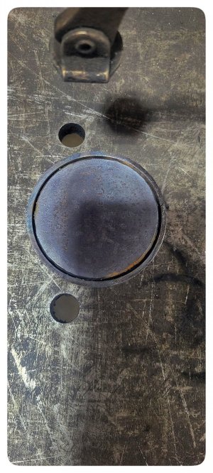
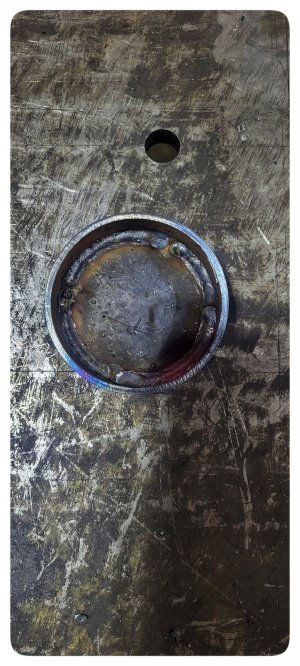
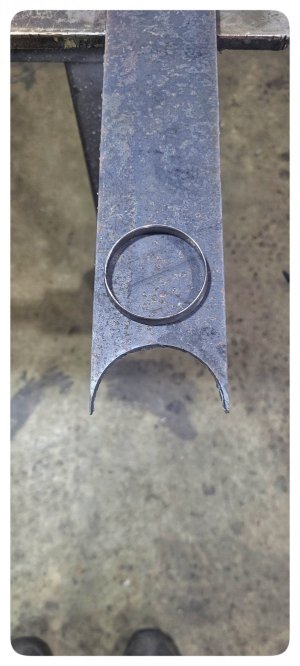
So I got the r8 shelf just about complete. I am going to try something I haven't yet tho, but apparently works well. Got a dimple die printing on the 3d printer so tomorrow I will dimple die the holes downwards. Hopefully works out good.

I'm torn between doing another, identical r8 holder below it, I have 1 more r8 collet holder, and I'm assuming I may collect a few more naturally.

Or just a shelf for end mills and such...

I will also likely either cap the end tubes, or add a piece of angle and drill some holes for chuck keys / misc.
 

Attachments

  • 1000005904-01.jpeg
    1000005904-01.jpeg
    276.1 KB · Views: 12
  • 1000005906-01.jpeg
    1000005906-01.jpeg
    533.9 KB · Views: 12
  • 1000005907-01.jpeg
    1000005907-01.jpeg
    604.6 KB · Views: 12
Well I would highly recommend anyone with a 3d printer and a press or even a vise to print off some dimple dies. Works pretty effortlessly.(on 16g)

Opted to go for a shelf underneath with similar dimensions

The dimple makes it nice as the 1 1/8" hole now completely clears the r8 taper
 

Attachments

  • 1000005921-01.jpeg
    1000005921-01.jpeg
    448.5 KB · Views: 16
  • 1000005920-01.jpeg
    1000005920-01.jpeg
    464.1 KB · Views: 14
  • 1000005917-01.jpeg
    1000005917-01.jpeg
    383.5 KB · Views: 12
  • 1000005919-01.jpeg
    1000005919-01.jpeg
    502.6 KB · Views: 12
  • 1000005915-01.jpeg
    1000005915-01.jpeg
    440 KB · Views: 11
  • 1000005914-01.jpeg
    1000005914-01.jpeg
    260.3 KB · Views: 15
  • 1000005913-01.jpeg
    1000005913-01.jpeg
    281 KB · Views: 17
Got it under the mill, just need to pickup 4 bolts & drill the mounting holes. Will have to remove y axis dro so will be a little messing around.

Quickly levelled it but will give it a better go once the mills bolted
 

Attachments

  • 1000005971-01.jpeg
    1000005971-01.jpeg
    515.3 KB · Views: 13
  • 1000005972-01.jpeg
    1000005972-01.jpeg
    521.6 KB · Views: 13
  • ZomboDroid_20022024114358.jpg
    ZomboDroid_20022024114358.jpg
    671 KB · Views: 13
Got the other two bolts in, got the machine pretty damn level, and decided to make some chips

Started off with a piece of a bop stud & ended up with a 3/4" shank fly cutter that holds a 1/2" tool bit.

Did all the milling with a 3/8" roughing mill so surface finish isn't amazing but happy with what the South bend left on the rounds.
(Sorry about my crude angle measurement):eek:
 

Attachments

  • 1000006006-01.jpeg
    1000006006-01.jpeg
    616.9 KB · Views: 11
  • 1000006008-01.jpeg
    1000006008-01.jpeg
    545.2 KB · Views: 9
  • 1000006005-01.jpeg
    1000006005-01.jpeg
    395.9 KB · Views: 12
  • 1000006004-01.jpeg
    1000006004-01.jpeg
    309.3 KB · Views: 105
  • 1000006001-01.jpeg
    1000006001-01.jpeg
    297.8 KB · Views: 12
What is this thing and what are you doing with it???

1000006004-01-jpeg.44429
Seeing how far off from vertical I was. My other option was to just wing it lol.

I set it like so then brought the endmill down alongsidee the stock, marking it with a sharpie as I moved the x axis along the width, then pulled it out and hacked off most(should have took more)of it with the band saw

Sorry, still not following....... To accomplish what with respect to your fly cutter?
 
Last edited:
Spent the better part of yesterday and this morning messing around with chucks. Mostly my er32 collet chuck, I attempted to use it when building the fly cutter & realized the runout was extreme(.010-.015")

I believe when I first machined it(one of the first things I did after getting the lathe) that the backplate wasn't fully on the register. Lots of f*ckin around checking, and rechecking, and comparing with my r8/er32 collet chuck in the mill which is basically perfect & came to that conclusion.

So I pulled the chuck off and adjusted the backing plate after some research and got it down to .001-.0025"(measured on some 3/4" stock held in the chuck, and also a 3/8" & 12mm carbide endmill) which prob ain't great for a collet chuck but decided good enough for now and moved on.

Checked runout in the 3jaw - .010" ouch, removed the backing plate & clocked it to a different hole and got it down to .003"

Then realized the 4jaw wouldn't fully register so a lot of time spent cleaning the internal threads & finally got it to register

I decided to check my headstock Jacobs chuck and it only screws on about halfway, cleaned the threads for a long time just to get it there, I think I'll have to set it up on the lathe and maybe ream the threads turning the lathe by hand? Future me problem.

Decided after all the messing around to do a feel good project so I made a handle for the southbend to replace the top nut on the qctp, will be much better then using a crescent wrench.

Also mounted my little shop vac on the wall between the lathe & the mill.
 

Attachments

  • 1000006024-01.jpeg
    1000006024-01.jpeg
    375.9 KB · Views: 10
  • 1000006025-01.jpeg
    1000006025-01.jpeg
    484.2 KB · Views: 9
  • 1000006026-01.jpeg
    1000006026-01.jpeg
    443.9 KB · Views: 9
  • 1000006027-01.jpeg
    1000006027-01.jpeg
    453.4 KB · Views: 10
Checked runout in the 3jaw - .010" ouch, removed the backing plate & clocked it to a different hole and got it down to .003"

It is perfectly normal for machinists to clock their chucks like that. If it works it works right?

I use a letter punch to make the Letter "O" next to any one of the cam sockets on my D1-5 spindle nose. Then I mount the chuck and put a sharpie mark on the chuck next to the stamped O and then measure runout. I do at each stud in sequence till I know which stud next to the O provides the lowest runout. With 6 studs to try, odds are good one will be notably better than the others. A retest is looking for differences is required. Different results suggest a hidden problem that needs to be solved before finally putting a punch mark next to the best stud. After that, you just line up the index O's whenever you reinstall that chuck.

I'm glad you found one better than the others.
I can't say for 100% sure. But I'm 95% sure when I got the lathe I disassembled the chuck completly to clean it and can't remember if I marked it to reorientate. Should have obviously checked before now but haven't made anything in it too important, or anything that I didn't cut off after turning. Still funny tho!

I put a faint scribe in the 3jaw/backing plate and the er32 collet chuck as well.

I went out with full intentions on getting the rotary table & chuck mounted and centred on the mill but of course didn't have a stud short enough/threaded long enough to cut in the hold down kit so threaded some more 1/2 rod & cut two to length.

Vise will also have to move over 2-3" and I'm thinking I'll permanently leave the vise off to the side so when I put the rotary table on in the future I don't have to mess with the vise. Won't hurt to put a little wear in the ways on the side either

Want to mill a spline wrench using it for the RF45 so hopefully tomorrow's project
 

Attachments

  • 1000006040-01.jpeg
    1000006040-01.jpeg
    298.1 KB · Views: 8
  • 1000006041-01.jpeg
    1000006041-01.jpeg
    261.3 KB · Views: 8
  • 1000006042-01.jpeg
    1000006042-01.jpeg
    304.1 KB · Views: 8
What is this thing and what are you doing with it???

1000006004-01-jpeg.44429
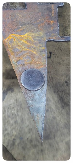
I should have also said it's a magnetic angle protractor. I think this style welders use, not sure if that's who it's aimed towards.

I bought it years ago welding on new link tabs on a 4runner rear axle and I think this may be the first time I used it since.
 
Last edited:
Back
Top