• Scam Alert. Members are reminded to NOT send money to buy anything. Don't buy things remote and have it shipped - go get it yourself, pay in person, and take your equipment with you. Scammers have burned people on this forum. Urgency, secrecy, excuses, selling for friend, newish members, FUD, are RED FLAGS. A video conference call is not adequate assurance. Face to face interactions are required. Please report suspicions to the forum admins. Stay Safe - anyone can get scammed.

JCDammeyer's 42 projects

One idea I've had is first use the boring bar to cut the Long Arm side to bearing press in diameter with table XY locked. Then clamp down a piece in place of the part, swap the cutter around and cut a disk the diameter of the bearing which will still be on axis with the spindle. Use the previously cut piece to size to a tight slip fit.
Then fasten the piece down on that disk and bore the opposite side after turning the cutter back in to do a hole instead of a plug. Now the two holes should be on axis and in line.
If I bolt a couple of 1-2-3 blocks against the straight edges I should be able to line up the planetary drive clamp plate so that hole is also bored concentric with the spindle.
All with the XY table locked in place.
I think it's all about jigs. A lot of work for one piece. But then one could make 10 or 100 pieces too.
 
One idea I've had is first use the boring bar to cut the Long Arm side to bearing press in diameter with table XY locked.
First I thought I'd better print out a model so I can figure out how to set things up.
1726883420922.png


This is what I was thinking of using after I have a preliminary hole. I don't have an end mill long enough to go all the way through this thing which is just under 1.75" thick.

1726883471383.png


I'm wondering if there are suggestions on how fast to turn it and how fast to move it down.
One thought is 300 RPM and a feed rate of 0.1 ipm.

N6 G86 X0. Y0. Z-1.625 R1.5 F0.1 P0
 
I'm wondering if there are suggestions on how fast to turn it and how fast to move it down.

I would use an outside hole for the boring bar which should allow the slide to be closer to center. I always like things as rigid as possible.

For speeds N feeds, I usually use the charts to find the recommended surface speeds and feed rate for the material and cutter, and then adjust slower or faster by feel and ear till the machine is happy. A boring head is just an inside out lathe. In other words, the ID of the hole is the same as the OD of a bar mounted in the lathe, and the feed rate and depth of cut are also the same.

FWIW, I hate those brazed carbide boring bars. I wish some outfit would make HSS boring bars for boring heads or boring bars for boring heads with Carbide inserts.
You make a good point. An HSS cutter would work better here and be way more robust for a 62mm diameter hole. I've made bars like that for my lathe work. No reason I couldn't mount it into the mill boring head. BTW, that cutter is in the middle only because that's where it was used last. It was just for the picture.

I did some 3D printing tonight to get a feel for the part with the bearings installed. I think I'll turn the aluminum spindle next to get a feel for alignment. These bearings just slipped into the plastic recesses.

1726897338443.png


1726897378523.png
 
A boring head is just an inside out lathe. In other words, the ID of the hole is the same as the OD of a bar mounted in the lathe, and the feed rate and depth of cut are also the same.

Ah. So if I'm turning here's the best case for high production turning.
1726936840628.png


Reducing surface speed to a more reasonable 190 fpm with HSS gives me 300 RPM, a 0.02" depth of cut and essentially 0.01" IPR. So if we move 0.01" down in one rev and since the tool would be spinning at 50 RPS it moves down 50 * 0.01" or 0.5 IPS which is 30 IPM feed rate. That seems really fast for boring.
1726937105179.png
 
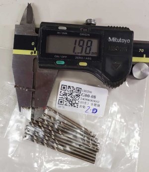
Currently working with AliExpress seller to either exchange or replace drill bits. Supposed to be 2.5mm which is what I broke a few weeks ago.
DrillBits_2mm.jpg
I should probably just order a set of ten 2.5mm bits but I don't want to receive another set of ten 2.0mm
 
Ah. So if I'm turning here's the best case for high production turning.
View attachment 52019

Reducing surface speed to a more reasonable 190 fpm with HSS gives me 300 RPM, a 0.02" depth of cut and essentially 0.01" IPR. So if we move 0.01" down in one rev and since the tool would be spinning at 50 RPS it moves down 50 * 0.01" or 0.5 IPS which is 30 IPM feed rate. That seems really fast for boring.
View attachment 52021
300/60=5rps, 3ipm...
First one is .014 chipload, second like you said is .01.
Id gun for a .005 chipload @300rpm -> 1.5ipm feed, but im no machinist. :P

To get .014 chipload @300rpm would be 4.2ipm
 
Last edited:
I should probably just order a set of ten 2.5mm bits but I don't want to receive another set of ten 2.0mm

If I was you I'd just go get one good drill at your nearest jobber and be done with it. I stopped playing games with Ali, Amazon, and ebay years ago. I've been buying one or two good drills at a time ever since.

It certainly isn't the most economical way to do it. Especially not if you add in all the gas to buy 1 or 2 drills and a tap at a time. But I just can't spend a thousand dollars all at once to buy a full set of good drills. And lord knows what a good set of taps would cost. So I buy taps and drills as I need them and it doesn't seem to hurt as much that way.
I have a complete set of good drills in Inch, Numbered and Lettered. Also two sets of metric. But good drills or not when you break one due to stupidity (forgot to set it as peck drilling into aluminum) then one pays the price.

I've already ordered another 10 of the little puppies. At $3.69 with free shipping I kind of think why not. But I'm stressing that they better be 2.5mm or I'll claim for all my money back. Having an extra 10 pieces of 2mm at $0.37 each isn't a killer for me.
 
Machining question:
This is what I need to make
1726976108819.png

The 14mm keyed bore needs to be concentric with the outer part within 0.002" and of course closer is better. Obviously the mounting plate at the end needs to have the flat surfaces at 90 degrees to the shaft section.

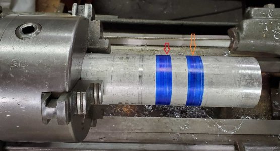
Now this is what I have faced off in the lathe but I think it's too far out for being held well. The yellow arrow points to the back face of the part. The red arrow points to where I could saw this off to still give me clearance from the chuck jaws. But I'd be wasting about 1" of the 2" diameter bar.
J2SpindleRawStock-Cuts.jpg
My steady rest is not a roller bearing and the brass pads would wear through the aluminum so that's out.

Here's what I'm thinking of doing.
1. Centre drill and drill to 13mm for the depth of the 14mm diameter section.
2. Bore to the 14mm ID and slip fit on planetary drive shaft (w/o keyway).
3. Use the tailstock center to hold the end steady.
4. Turn to the scribe line to the right of the yellow arrow to the target diameter.
5. Remove and use the band saw to cut it to the left of the orange arrow.
6. Place in chuck and face off and drill/bore to the larger diameter so the broach will clear.

I believe that will keep the inner and outer part concentric with each other.

Normally when I do this sort of project I's use a 14mm keyed mandrel between centers.
Mandrell_14mm_5mmKey.jpg
But I'd have to make a new one that is longer and has a 4mm slot rather than 5mm. This one was made for a much smaller pulley to be turned between centers.

Suggestions?
 
Couldn’t you take a skim coat off then cut to size or then use the brass pads?
It’s what John Wayne would do!
 
Couldn’t you take a skim coat off then cut to size or then use the brass pads?
It’s what John Wayne would do!
To use the 3 point steady rest the 3 pads essentially have to have zero clearance but of course the cutting process will tend to try push the bar against the brass pads. I've only use the steady rest for steel parts. The one I made for my Gingery Lathe has bearings.

If this spindle was steel I think the steady rest would be perfect.
 
The long pink arm is what screws onto this spindle I need to make. Any play or non-concentric behaviour affects the end point of the arm. As long as that spindle and face are turned in one setting and the cross slide moves properly perpendicular to the lathe axis it shouldn't have any wobble.

1726978183843.png
 
It wouldn’t take much more than a 1/2 inch or so though.
I could heat the steel coller to slip it onto freezer cold aluminum. Then turn it to be concentric. Getting it off afterwards might be tough. Heat it and the AL expands more. Press it off maybe. I have a 3T press.
 
Back
Top