• Scam Alert. Members are reminded to NOT send money to buy anything. Don't buy things remote and have it shipped - go get it yourself, pay in person, and take your equipment with you. Scammers have burned people on this forum. Urgency, secrecy, excuses, selling for friend, newish members, FUD, are RED FLAGS. A video conference call is not adequate assurance. Face to face interactions are required. Please report suspicions to the forum admins. Stay Safe - anyone can get scammed.

JCDammeyer's 42 projects

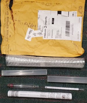
Meanwhile, the email from Seawings Express this morning took me to the airport. Grabbed the paperwork and walked to customs inside the airport. Rubber stamp, no money needed, back to Seawings to pay the $20Cdn shipping.

Total cost savings about $30US as Little Machine Shop used snail mail to ship to Blaine Washington for $12.73US.
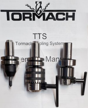
The one on the left is 6mm and now permanently holds the 90 degree chamfering carbide cutter. In the middle the JT holder and a 3/8" drill chuck. All I had in Tormach was the 1/4" chuck which is too small for 7mmm and 8mm drill bits which I need for the robot arm etc.
The one on the right is the original Tormach holder without the Tool Changer slot and the bevel on the end. I really was at the front of the line when I first invested in Tormach tooling.

TormachTools.jpg
 
Last edited:
Meanwhile, the email from Seawings Express this morning took me to the airport. Grabbed the paperwork and walked to customs inside the airport. Rubber stamp, no money needed, back to Seawings to pay the $20Cdn shipping.

Total cost savings about $30US as Little Machine Shop used snail mail to ship to Blaine Washington for $12.73US.
The one on the left is 6mm and now permanently holds the 90 degree chamfering carbide cutter. In the middle the JT holder and a 3/8" drill chuck. All I had in Tormach was the 1/4" chuck which is too small for 7mmm and 8mm drill bits which I need for the robot arm etc.
The one on the right is the original Tormach holder without the Tool Changer slot and the bevel on the end. I really was at the front of the line when I first invested in Tormach tooling.

View attachment 54019
My future involves TTS holders...
 
My future involves TTS holders...
I really like them. And I'll like them even more when I get my power drawbar project (#42) finished. Mind you now that I have the tool setter on the table it's not such a big deal for repeatable insertions of different tool holders. But that movement over to the tool setter and then waiting for it to measure the tool is also tedious. Nice to have the common tools all measured and just use that length.
 
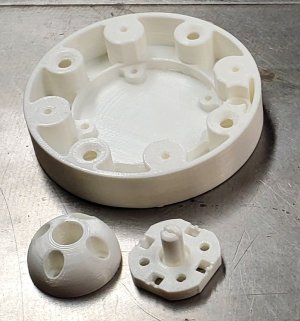
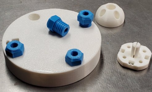
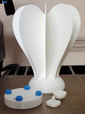
Printed off the 3 main base parts and then the 4 levelling feet. Tomorrow morning I'll start the big wing assembly. Still need to order a few electronic parts. The PC board is coming from Poland via snail mail so that will be a few weeks. Same with the stuff from AliExpress.
 

Attachments

  • BasePartsPrinted.jpg
    BasePartsPrinted.jpg
    101.5 KB · Views: 3
  • LevelingFeet.jpg
    LevelingFeet.jpg
    277.4 KB · Views: 3
Added another project to the list.
I've ordered his PC board. Got the Fusion360 files for the design and a friend will change them to STEP files for me.
Ordered the strain gauges and spirit level from AliExpress.
I think I'm crazy...
There! Done. Waiting for PC boards, parts and need to source a 10mm OD aluminum tube 150mm long.

Initial indications are that it's quite expensive. It's used to stiffen the wing assembly. Might be cheaper to buy some aluminum rod, turn it down to 10mm and just drill an 8mm hole in one end. Only needs to be about 30mm deep.

3DPrintingDone.jpg
 
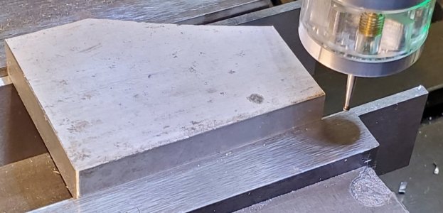
On the LinuxCNC group Andy Pugh posted a youtube video on using a probe to determine the shape of a part. He included the G-Code. I was certain that I'd posted a link to that but maybe not.

Anyway. I didn't break my probe this time. I converted hsi G-code to imperial units. It managed to do 3 sides and then hung up in the bottom RH corner. A screwdriver placed in the way at the right point and on it went the rest of the way around.

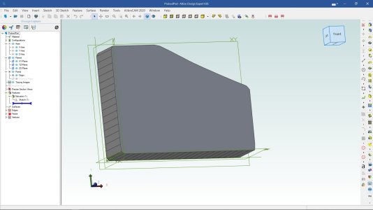
After that it continued the rest of the way around. The resulting file inserted into Alibre (Fusion360 can do this too) and then a bit of cleanup and bingo the part is moved so the X=Y=0 origin is on the bottom left hand corner.

StuckOnCorner.jpg

Here's the rendered part.

RenderedPart.jpg
The CSV file (as a .txt) with X,Y test points is attached in case someone wants to play with their favourite CAD program.
 

Attachments

Last edited:
So I have yet another project just as I am almost finished with the Herbus plant starter.
We have (or had) squirrels in our attic. Apparently since our house was vacant for two weeks they decided to move in. No rent payments. Sneaky.
Couldn't see any ingress point from the ground. But there was a slightly suspicious point. Out comes the ladder to look again where I'd put mesh to keep the rats out. Mesh was fine.

Move ladder over and look above the gutter. Ah ha. Not really visible from the ground nor from the roof and only just with a telephoto lens from the upper driveway.

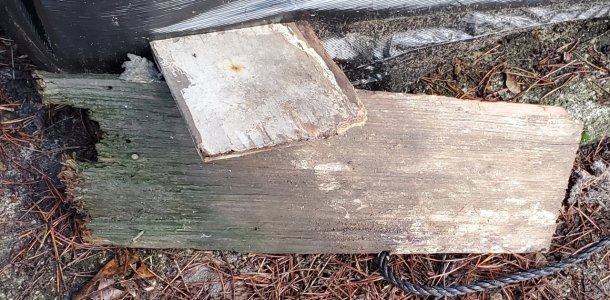
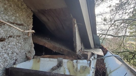
This piece attached to the plywood soffit had rotted and fallen down.
HoleCoverOriginal.jpg

With it out of the way it's easy to see how big an entry there is now.
HoleRoofEntry.jpg

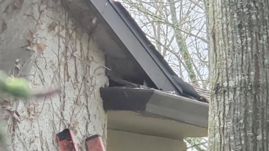
With the triangular piece moved towards the wall the view from the ground with the 10x setting on the cell phone camera shows just how hard it would be to spot that this was a hole.
HoleGroundView-1.jpg

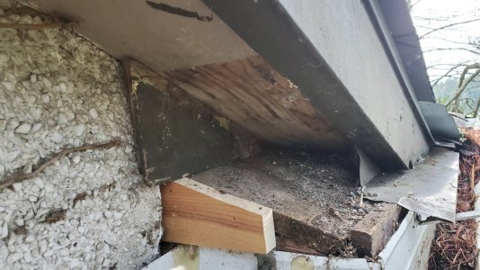
Now plugged up. The plywood piece can be pushed out if the squirrels are still in the attic. But it's tight enough that they likely couldn't pull it out from outside so they will have to sleep in a tree tonight.
HoleCovered.jpg

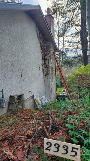
Now from the back driveway it's still not really possible to see the hole covered up. Only the piece of wood shows that there's something different there and even that's hard to see.
HoleGroundView-2.jpg
 
= 2025, I love that kind of math trivia. Tks
I may steal it as my own. I'm sure the kids will believe it's mine! At least for about 10 seconds.
 
Last edited:
Back
Top