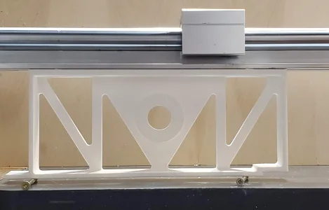
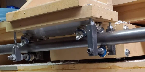
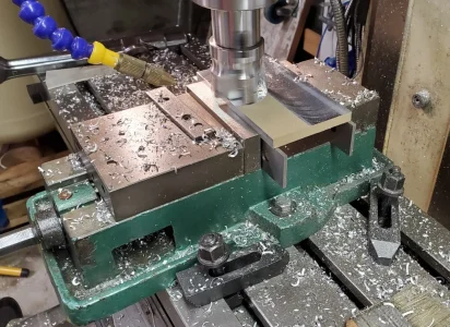
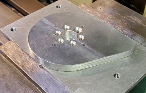
Well aside from one broken 2.5mm drill bit and one broken 3mm tap and accidentally changing the X=0.000 location the result is passable but really a piece of crap.
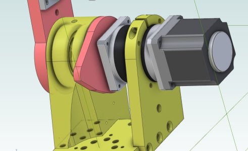
This J1 Tension Plate is designed to compress the two tapered bearings and connect the motor drive along with a tab to hit a limit switch. Here's the CAD drawing of it.
View attachment 51503
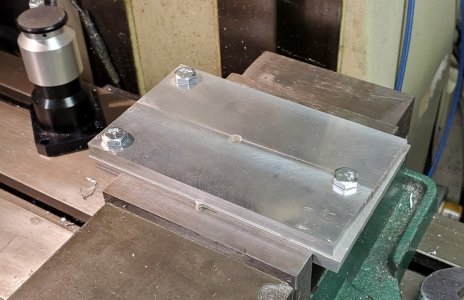
Starting with a sacrificial mounting plate and the target part drilled in 3 points and bolted down. Part hold down hole also in place.
View attachment 51498
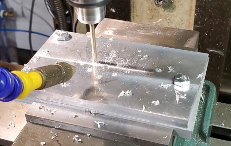
Now I drilled the 3.2 and 3.5mm holes and counter sunk them.
View attachment 51499
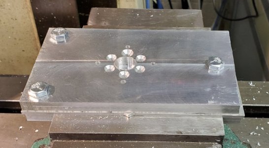
First mistake was the initial depth of the counter sink was too deep. I had actually stopped it there and started cranking it down manually when I realized the target hole from the CAD drawing was way wrong. Edited the G-Code and set new depth for all 6 holes and then ran it again. Much better.
View attachment 51500
I had also spiral bored out the middle hole which is a clearance fit over a 14mm shaft so nothing special but somehow both my zero and depth were off. Didn't quite cut into the mounting place. And worse is in readjusting the Z=0.000 using the drag paper under the cutter approach, I accidentally zero'd X. At that point it was a bear to get it recentered since my original reference point was off and I didn't think to use the probe on the hole. Sigh.
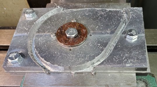
Next step Profile the outside. Clamp down, Z=0.000 means it should now cut into the bottom plate by a teensy bit. Not...
View attachment 51504
After all is said and done and some file work it's usable but I'm not happy.
View attachment 51501
The backlash and positioning really didn't make for the greatest cut. A depth of 0.1" per pass and 5 IPM with a 1/4" two flute end mill. I likely should have left 0.010" and then done a single pass around with a 1/4" four flute end mill.
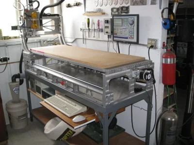
I may have to restart project #42 and add ball screws to the mill. The backlash is killing me.

