-
Scam Alert. Members are reminded to NOT send money to buy anything. Don't buy things remote and have it shipped - go get it yourself, pay in person, and take your equipment with you. Scammers have burned people on this forum. Urgency, secrecy, excuses, selling for friend, newish members, FUD, are RED FLAGS. A video conference call is not adequate assurance. Face to face interactions are required. Please report suspicions to the forum admins. Stay Safe - anyone can get scammed.
You are using an out of date browser. It may not display this or other websites correctly.
You should upgrade or use an alternative browser.
You should upgrade or use an alternative browser.
Tool Vevor Drill Bit Sharpener Improved
- Thread starter TorontoBuilder
- Start date
Tool
TorontoBuilder
Sapientia et Doctrina Stabilitas
I have some STL files of the test parts if anyone wants to test the prototype.
Download folder is here
I'll also post pdf files of the parts drawings later
I updated the parts folder to include 4 new parts.
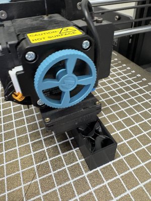
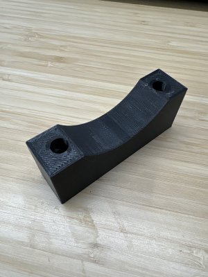
One is a generic motor support bracket that is intended to friction fit under the far end of the motor so provide additional support for using plastic only motor mount.
Then I've added a new "20G motor mount" that will allow for the proper positioning of the 20G wheel relative to the standard 13A/B/D grinder seat. The base set back 4mm and has extensions that insert into the slot in the base plate. It also has a boss to install a heat set insert for the cover screw.
I've added "20G B block" that centers over the chuck over the rear of the 20G wheel, and I've added a "20G A Block mount" which positions the standard A tool insert over the front edge of the 20G wheel.
The download folder is still found here
Does Yotabota need these printed?I updated the parts folder to include 4 new parts.
One is a generic motor support bracket that is intended to friction fit under the far end of the motor so provide additional support for using plastic only motor mount.
Then I've added a new "20G motor mount" that will allow for the proper positioning of the 20G wheel relative to the standard 13A/B/D grinder seat. The base set back 4mm and has extensions that insert into the slot in the base plate. It also has a boss to install a heat set insert for the cover screw.
I've added "20G B block" that centers over the chuck over the rear of the 20G wheel, and I've added a "20G A Block mount" which positions the standard A tool insert over the front edge of the 20G wheel.
The download folder is still found here
TorontoBuilder
Sapientia et Doctrina Stabilitas
He does not have a 20G wheel as far as I know.Does Yotabota need these printed?
If he wants to sharpen up to 20mm drills he needs a 20G wheel, and ER25 chuck and Er14-20 collets to do so, with the 20G mod parts.
He has missed our bulk order, so I think he doesn't need that capacity perhaps.
TorontoBuilder
Sapientia et Doctrina Stabilitas
I should have both 13D parts and 20G parts in hand by the end of the day tomorrow, after I return from the woodworking show.<standingdown/>
I'll see if I can just slam in some 8mm bolts to do a down and dirty test grind tomorrow night with the 13D conversion. I'll need to go to brother's to secure a larger bit to test the 20G setup. I'll have to improvise on the bit projection for wider the 13mm drills. But I think that the projection is the same as the drill diameter on the normal set-up. The 20G may just cause the addition of a mm or so
TorontoBuilder
Sapientia et Doctrina Stabilitas
NAH lets just have @DavidR8 print the support block too. Low infill, low wall count, down and dirty is all you need. Then it can be left in place.It's not often I do anything over 1/2 inch so I just sharpen then by hand.
I made a wood block to support the motor while we test fit the printed parts.
I am sorely tempted to make parts of plastic and leave them in place, after I've printed optimized parts. If I wont need to mill metal why would I...
"Why would I",,,,,, Your a funny guy! lolIf I wont need to mill metal why would I...
I will probably fit the support and then MILL a couple of slots in the base for screws up into the support.
TorontoBuilder
Sapientia et Doctrina Stabilitas
"Why would I",,,,,, Your a funny guy! lol
I will probably fit the support and then MILL a couple of slots in the base for screws up into the support.
If you want to do that I'll modify the part to accept a heat stake insert, to do it right.
This one?NAH lets just have @DavidR8 print the support block too. Low infill, low wall count, down and dirty is all you need. Then it can be left in place.
I am sorely tempted to make parts of plastic and leave them in place, after I've printed optimized parts. If I wont need to mill metal why would I...
TorontoBuilder
Sapientia et Doctrina Stabilitas
yepThis one?
View attachment 57990
TorontoBuilder
Sapientia et Doctrina Stabilitas
I have a new part "motor support with insert holes", that has 5mm heat stake insert in the top. The holes are 15.1 mm from the edge, and 58mm apartThis one?
View attachment 57990
Rats. Old one is in progress.I have a new part "motor support with insert holes", that has 5mm heat stake insert in the top. The holes are 15.1 mm from the edge, and 58mm apart
View attachment 57995
Seems I should end it.

TorontoBuilder
Sapientia et Doctrina Stabilitas
What inserts are needed here?
View attachment 57997
The insert on the side is 5mm insert.
The bottom of the motor mount is threaded into the plastic since the hole is deep it should hold fine, and an insert doesn't fit in the projection.
The top of the tool blocks are have an 8mm thread profile for now. I did not select an insert hole for it yet since it is prototype and sadly because I don't have 8mm inserts at the moment. I do have a buttload of 8mm taps to run thru the threads though.
The 2 holes on either side of the 8mm threaded hole are for 5mm guide rods. The guide rods are loctited or superglued into the hole in the motor mount. The 8mm grub screws need a profile machined in them and roll pins to hold them in place in the motor mount.
TorontoBuilder
Sapientia et Doctrina Stabilitas
Mine are ready to install.

TorontoBuilder
Sapientia et Doctrina Stabilitas
My parts were printed on a printer that had not been calibrated, and I'm finding the 28mm bores wont accept the chucks without chamfering and sanding.
@DavidR8 can you let me know if this is an issue when you visit @YotaBota please
My 8mm threads formed very well, and I ran them thru with one of my many 8mm taps. The tool insert block snapped right into the block holder...

