-
Scam Alert. Members are reminded to NOT send money to buy anything. Don't buy things remote and have it shipped - go get it yourself, pay in person, and take your equipment with you. Scammers have burned people on this forum. Urgency, secrecy, excuses, selling for friend, newish members, FUD, are RED FLAGS. A video conference call is not adequate assurance. Face to face interactions are required. Please report suspicions to the forum admins. Stay Safe - anyone can get scammed.
You are using an out of date browser. It may not display this or other websites correctly.
You should upgrade or use an alternative browser.
You should upgrade or use an alternative browser.
Radial engine build
- Thread starter PeterT
- Start date
Thanks. I keep reading that any oil will work, some people use used motor oil. I had some leftover (new) medium weight hydraulic oil so just keep a jar for this purpose. So far its worked very well on O1 but I am no expert. I do pre-heat the oil by heating up a dummy part & dropping in. With this oil the parts initially have a light soot coating but 90% of it falls off right in the oil & the rest comes off with no effort just cleaning prior to tempering, so that's a plus. For some reason this oil seems to smoke less but that could also be the small parts I'm doing lately. I've also tried cooking oil but from reading it seems like its more about the initial quench temp than the lower viscosity (ie. avoid cold oil). The cooking oil makes your shop smell like french fries if that's a plus LOL but it also can get a gamey rancid smell over time. I cant recall exactly but seems like the part cleanup was a bit more stubborn.
I don't have a graduated hardness kit for scratch test to verifying RN hardness. I use a spare crappy file. If it skates across then I call it good. My toaster oven is only good for 425-450F so that's all I can get - which corresponds to the light straw which is most things I do. If I wanted softer (higher temp) I'd have to do something else for tempering. I'd love a HT oven for better control but hard to justify the cost for what little I do. When I did my cam plates (A tool steel) I sent them to a knifemaker dude who has the whole HT enchilada, oven, salt bath, clamping plates... Hope this helps, good luck.
I don't have a graduated hardness kit for scratch test to verifying RN hardness. I use a spare crappy file. If it skates across then I call it good. My toaster oven is only good for 425-450F so that's all I can get - which corresponds to the light straw which is most things I do. If I wanted softer (higher temp) I'd have to do something else for tempering. I'd love a HT oven for better control but hard to justify the cost for what little I do. When I did my cam plates (A tool steel) I sent them to a knifemaker dude who has the whole HT enchilada, oven, salt bath, clamping plates... Hope this helps, good luck.
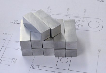
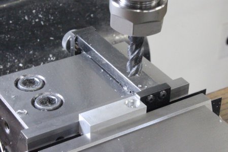
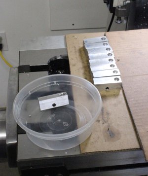
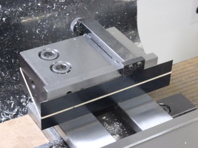
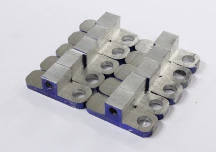
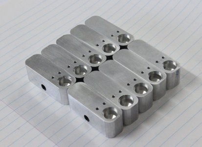
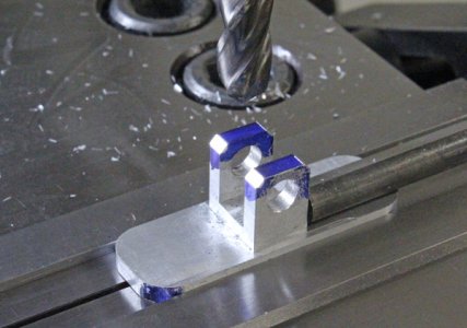
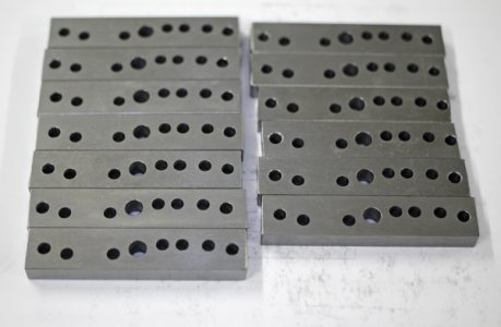
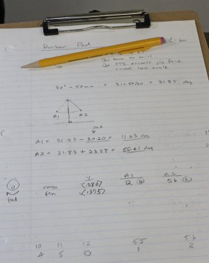
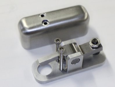
Looks like I forgot to post pics of the rocker perch's. I think they were done May-ish. This will make more sense in conjunction with the rocker arms which I just finished, but need to organize pics. The perch's are made from 6061. I have the valve hole drilled & counterbored which aligns to the head. But I'm still mulling over the pushrod hole on the other end so un-drilled. I made alignment jigs for the funky 3D angle of pushrod entry. The original design calls for pushrod tubes which I like. I'm not sure they circulate lubrication oil vs maybe just contain the mess a bit. But I'm not fond of how he retains the tubes into the perch with a teeny M2 setscrew. I'd like some kind of dampening O-ring but there isn't much material meat to play with anywhere. Same thing for the bottom end where the tubes meet the bronze lifter bushings. This is why most radials I see are tube-less'. I could go that route too & make slightly larger section pushrod from thin wall steel tubes & ball ends. I need to have the assembly in front to resolve this stuff so kicking the can down the road for now.
Attachments
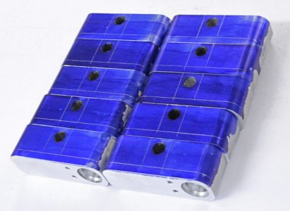
More machining steps. The footprint of the perch matches the rocker covers.
Attachments
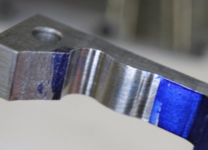
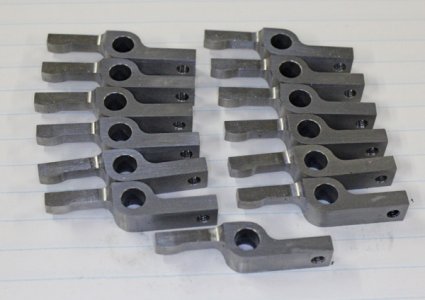
Here we go with rocker arms.
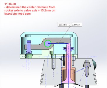
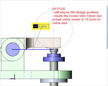
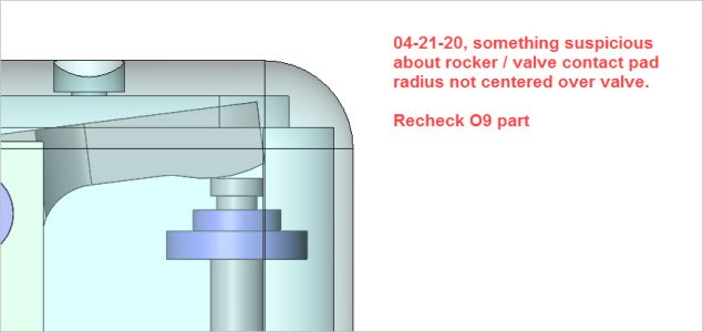
When I made a prototype directly from the plans (a long time ago) I figured I must have messed something up because the contact pad was not properly centered on the valve stem. I did modify the heads slightly, but didn't mess with any of this core geometry.
What makes this engine a bit funky is he uses some parts from the bigger 9-cyl radial, some parts specific to 5-cyl only & some parts which are modified from the 9 cyl. I wish it was just one set of plans but it is what it is. I checked everything I could think of and also in conjunction with other parts of the assembly which must fit one another & came to the conclusion he had a rouge dimension. Unfortunately it was a critical dimension. It would have been a bad day to make all the rocker arms & have this issue crop up. Unfortunately I hear stories like this all too often on model engineering forums. Plans are generally made by hobbyists or transcribed from parts or workshop sketches. These plans were 99% accurate from what I can tell. European drafting standards are a bit differentthan ours & sometimes minimalist dimensioning. I've learned to validate as much as possible & make some testers before committing to batch mode. This is where CAD programs are really beneficial.
Attachments
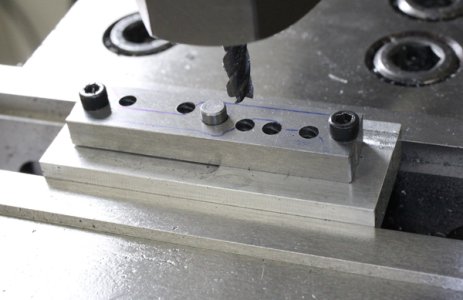
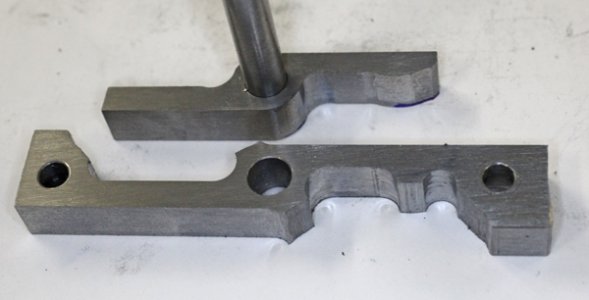
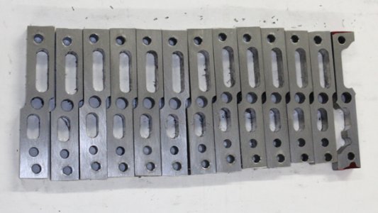
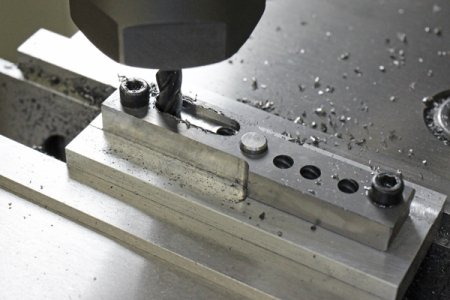
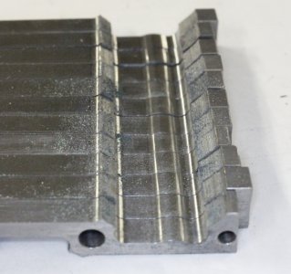
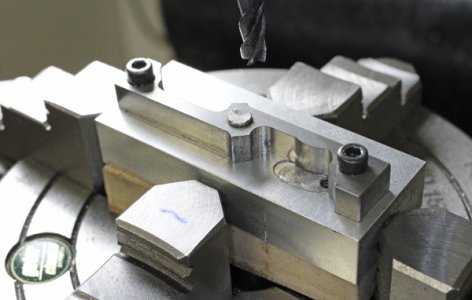
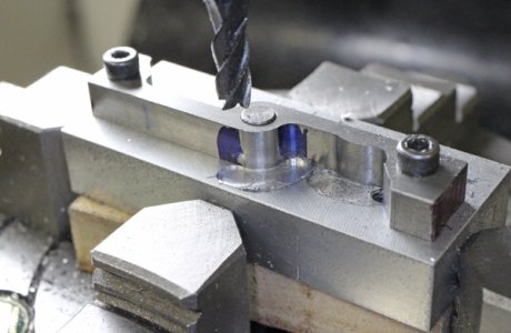
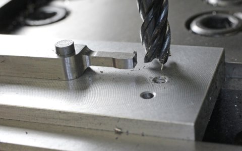
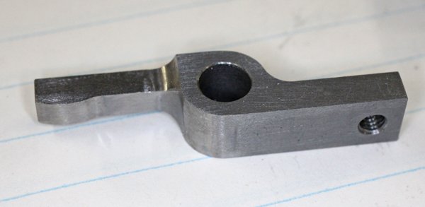
The rocker arms are made from 0.25" x 0.5" O1 tool steel. I got mine from KBC, happened to be Starrett brand. The curved contact pad area should be hardened but I'm not sure I can control the heat & quench that the whole arm wont be the same hardness, but I'll cross that bridge when the time comes. Here I'm pre-drilling all the (5mm) end mill slot holes so I can plunge before traversing. Lots of fiddly fillet transitions that have to tangent connect one another, so I found this to be a good method.
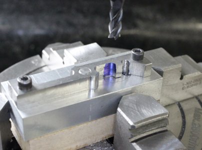
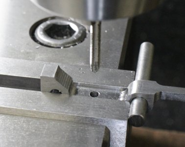
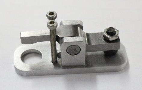
The jig is aluminum with very close fitting 6-21 capscrews to both align & clamp. Pins would be better but over this length it was quite accurate & simpler. Just lots of screwing & uncrewing with part swaps.
The jig is aluminum with very close fitting 6-21 capscrews to both align & clamp. Pins would be better but over this length it was quite accurate & simpler. Just lots of screwing & uncrewing with part swaps.
Attachments
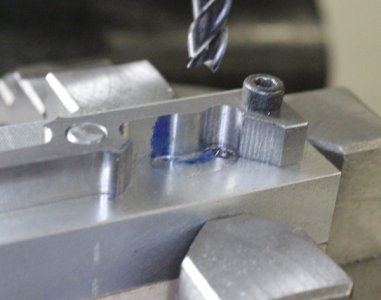
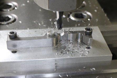
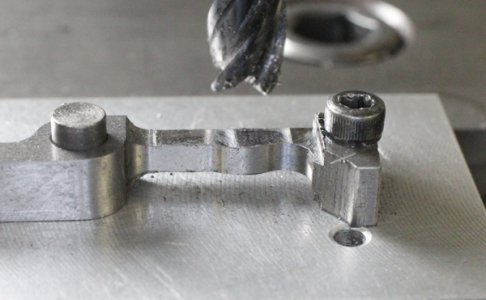
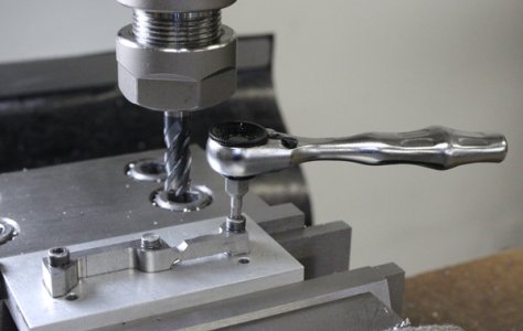
Same jig, back to the mill vise. Ball mill what will become fillet & flat mill the thin section. I'm hanging onto those original stock screw hold-down flat areas for as long as I can. I love my Wera mini hex ratchet wrench.
Attachments
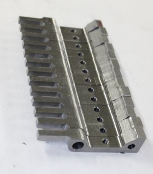
Lop off other end & mill to length.
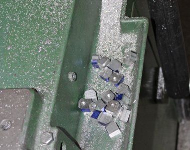
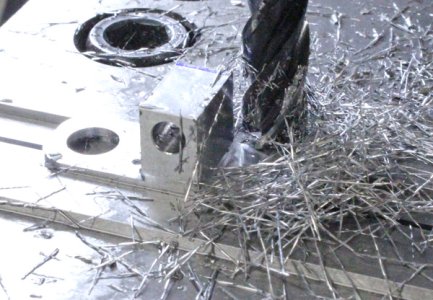
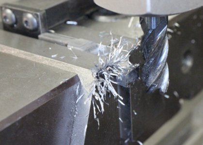
O1 has this crazy attribute while milling, the chips become semi magnetic & form these furry looking icicles.
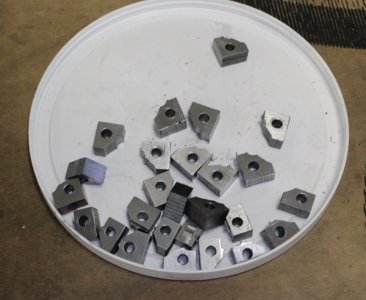
What can I make with the O1 scraps - mini toe jacks? LOL
O1 has this crazy attribute while milling, the chips become semi magnetic & form these furry looking icicles.
What can I make with the O1 scraps - mini toe jacks? LOL
Attachments
Last edited:
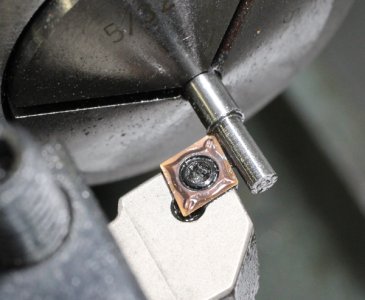
Rocker pushrod adjusters. I thought I might be able to make these from M3 capscrews. Unfortunately the dimensions of the socket head doesn't lend itself to necessary dimensions of the part. Also the fine print says the the ball end socket must be hardened so making them from scratch from 4mm OD O1.
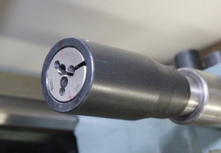
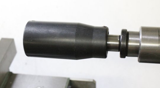
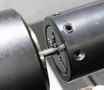
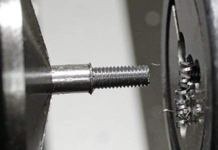
Basic turning to 3mm shank size. No way I was going to change headstock gears & cut M3 threads LOL. I broke out my made in India threading die head. The quality is kind of rough but for small thread like this it worked fine. I had to experiment trial & error with the die clam shell set screw to get the right thread fit.
Side note, when I made my own die head a while back with a tommy bar handle, I made a very snug fit to the nominal die OD. I think this may have been a mistake & might explain why my threads sometimes are slightly undersize even when I think I've adjusted the set screw properly. Possibly the die is opened up sufficiently but its getting collapsed again when I push it in the head. I think I'm going to make something better.
Once the threaded shank OD was turned to size I put lathe on low speed, some cutting oil & just fed die by hand. Once it gets close to the shoulder just let go & the head spins on the tailstock shaft. The M3 die is KBC euro brand. It cut very well.
Attachments
Last edited:

