-
Scam Alert. Members are reminded to NOT send money to buy anything. Don't buy things remote and have it shipped - go get it yourself, pay in person, and take your equipment with you. Scammers have burned people on this forum. Urgency, secrecy, excuses, selling for friend, newish members, FUD, are RED FLAGS. A video conference call is not adequate assurance. Face to face interactions are required. Please report suspicions to the forum admins. Stay Safe - anyone can get scammed.
You are using an out of date browser. It may not display this or other websites correctly.
You should upgrade or use an alternative browser.
You should upgrade or use an alternative browser.
Radial engine build
- Thread starter PeterT
- Start date
Not much radial machining over the past months because summer goes by so fast in Calgary. But I was cleaning up some files & found my wrist pin pics, so here they are.
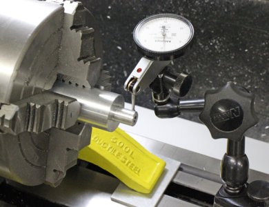
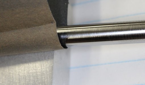
They were time consuming little buggers. O-1 drill rod in this ~5mm diameter is usually 0.001-0.002" oversize but its also usually oblong/elliptical in section by 0.001". So the stock is brought to dimension by lapping. The mating hole in the piston is reamed so they are the same, the wristpin OD is basically a hand-fit procedure. They shouldn't be loose enough to spin & its not easy to interference press them during assembly. So basically a tightish fingernail push fit.... which isn't in the Machineries Handbook lol
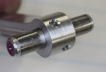
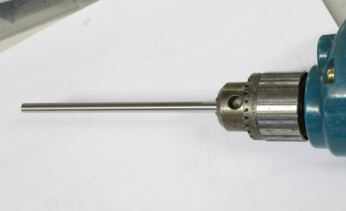
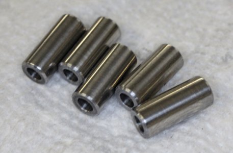
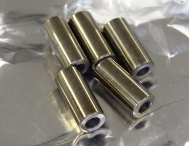
The ends are counter drilled slightly to receive aluminum end pads. I heat treated the pins manual mode with torch & oil quench. Then tempered in my mini (ex kitchen) toaster oven. No drama there, went very well. Then spun them in my drill for final finish. The little hole in the end pad is to allow any excess Loctite bleed, otherwise the parts can get fluid locked out of position. Once they are bonded the pads get turned to finish length & chamfered.
Attachments
-
 IMG_2794_edited-1.jpg248.8 KB · Views: 0
 -
 IMG_2795_edited-1.jpg214.4 KB · Views: 0
 -
 IMG_2796_edited-1.jpg169.9 KB · Views: 0
 -
 IMG_2808_edited-1.jpg228.2 KB · Views: 0
 -
 IMG_2811_edited-1.jpg251.9 KB · Views: 0
 -
 IMG_2812_edited-1.jpg206.8 KB · Views: 0
 -
 IMG_2864_edited-1.jpg235.9 KB · Views: 0
 -
 IMG_2869_edited-1.jpg191.7 KB · Views: 0
 -
 IMG_2870_edited-1.jpg146.9 KB · Views: 0
 -
 IMG_2818_edited-1.jpg204.9 KB · Views: 0
 -
 IMG_2817_edited-1.jpg169.3 KB · Views: 1
Last edited:
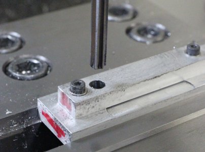
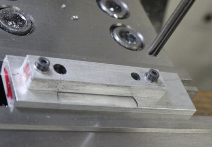
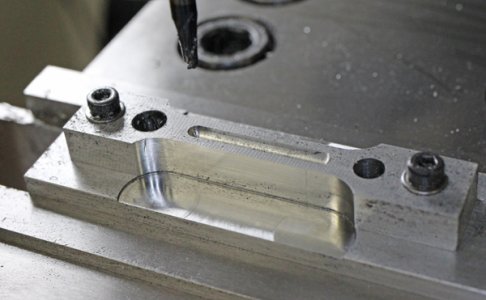
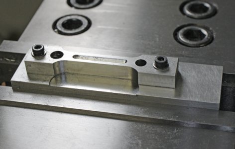
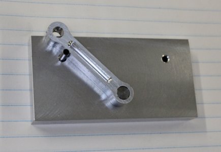
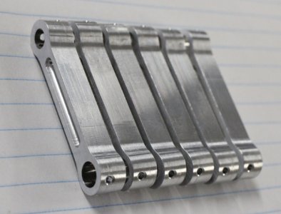
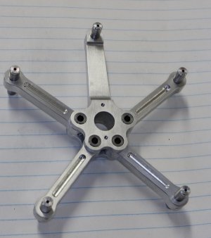
I redesigned my original link rod (LR) prototype & fixtures so it would be a bit easier to make. I started with sticks of 7075-T6 face milled to correct thickness. The outboard holes are just temporary hold-downs to get the wrist pin & crank pin holes exactly same length, reamed 5mm & 6mm respectively.
Attachments
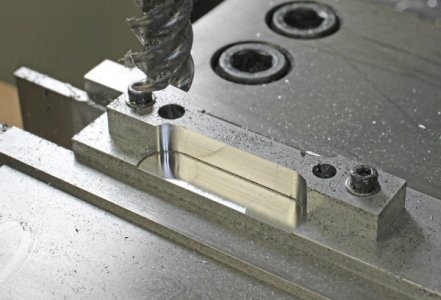
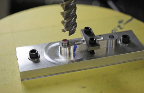
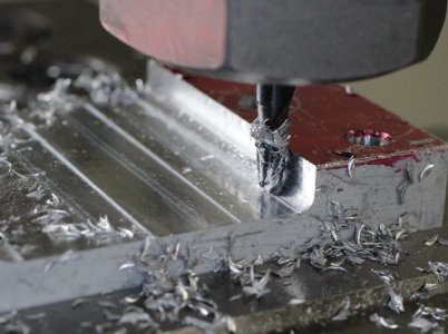
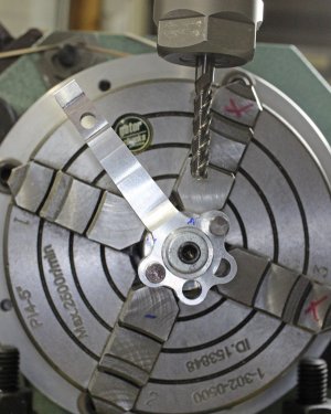
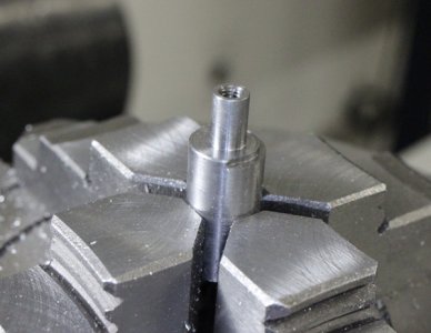
The LR ends were trimmed to remove excess material. This is where the rotary table tooling plate came in. LR was attached to fixture which was attached to tooling plate using coincident thread holes. Then it was a matter of milling the round over profile from 2 angle positions.
Attachments
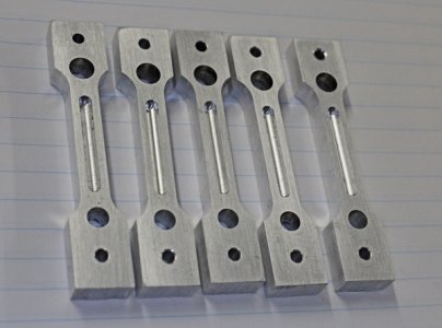
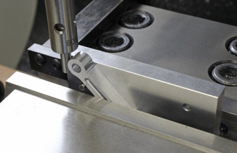
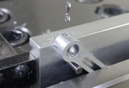
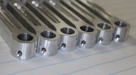
Another fixture to drill the oil lubrication weep poles. The lower end contains a dummy pin so it can rotate until the side makes contact with a positioning pin. Then its clamped in the mill vise this way. I have a stop on the jaw so the fixture goes in the exact same way each time a new LR is loaded. Then spot & drill the holes into the journal opening. I thought I would have to flip the LR to the other side so contemplated another stop pin there, but actually I just needed to flip the LR itself because the oil holes are off center so it was just a rinse & repeat job.
Attachments
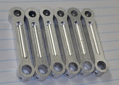
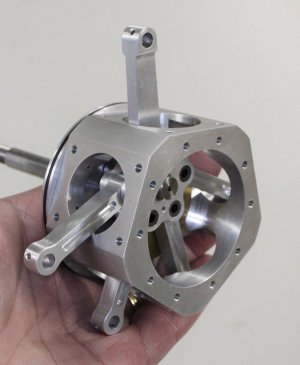
5 cylinders = 4 link rods + 1 master rod. Why is it when you make spares expecting to mess up, you don't mess up. But if you make the exact number of parts, you mess one up & have to remake one from start to finish? I'm becoming superstitious. And I guess its nice to have spares.
Attachments
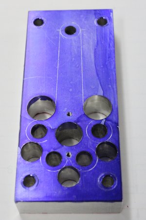
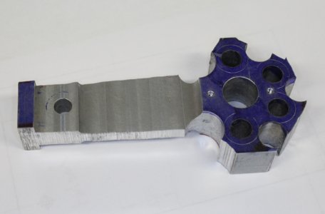
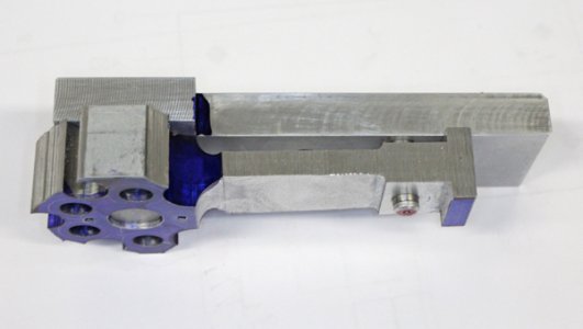
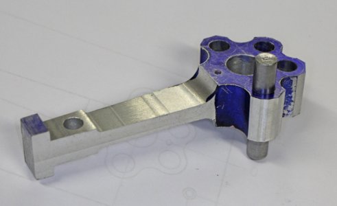
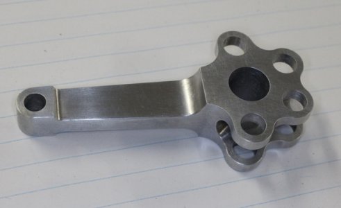
The master rod is made from 7075 aluminum. After the bar was face milled to width all the holes are drilled & reamed in one setup. Then some profile milling to thin the #1 cylinder main rod & fillets with ball EM. Then I band sawed the rough profile but left the thickness tab on the end for subsequent operations. A lot of these operations were kind of seat of pants - you have a rough plan of how to go about it, but you also have to think a few more steps down the line when it comes to gripping & fixtures.
Attachments
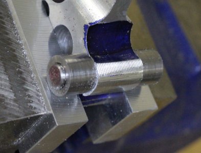
My initial plan was to file the knuckle rounds using OD buttons & the axle pins. So I milled some excess off. I like hand work but turns out this was a time consuming & I wasnt really happy with how it was coming out. Onto plan B....
Attachments
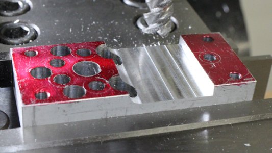
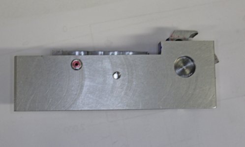
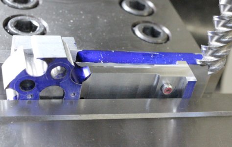
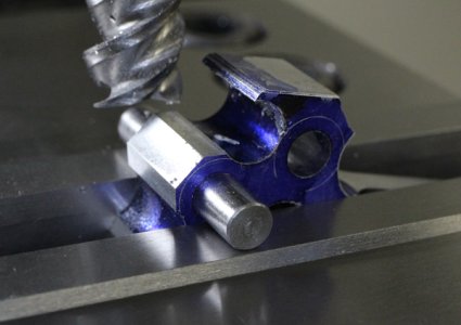
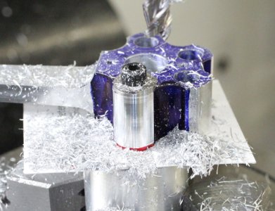
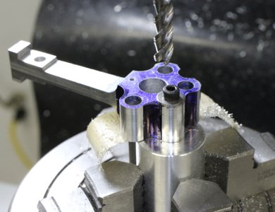
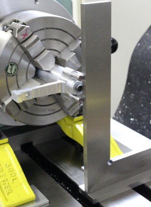
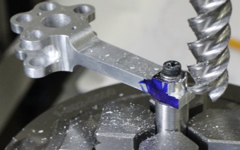
I made a fixture, dialed it into the RT & milled the profile. I didn't want the part to snatch so I stayed about 0.010" outside the radius & crept down on 0.050" increments. I had the tangent marks scribed on the blue so on final pass did the full cleanup. A bit more setup work but better results.
Attachments
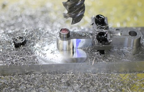
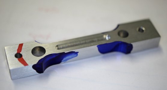
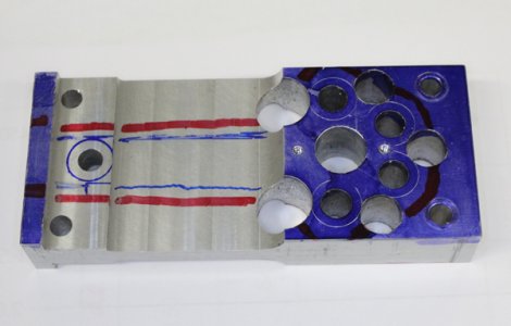
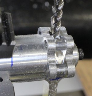
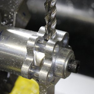
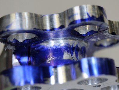
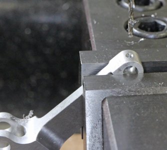
The slot for the link rods was a fussy bit of machining. I almost botched it on a few occasions. There are some odd angles & offsets, just the way the linkage geometry is. But I couldn't rotate & mill on one operation because of this it had to be done in 2 arc halves if that makes sense. I center slotted mostly to depth, then did the inside faces. Somehow it all worked out. One thing I didn't consider is all EM's have a slight radius & because the EM itself was offset, the resulting fillet at bottom of slot is exaggerated. My link rods weren't fitting well until I realized what was going on. The blueing makes it look worse than it was but took some careful hand filing with a safe edge to get the inside corner sharp without mucking up the faces. This is the difference between drawing something in CAD & making something it in real life LOL.
Attachments
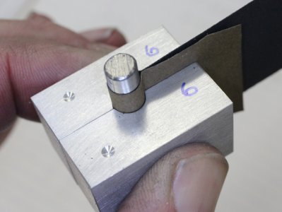
O1 type drill rod is about 0.001" oversize but its also typically oblong, not round. I messed around with a lot of lapping jigs & finally came up with this. Turns out simpler is better. I mic'd a bunch of my wet/dry paper & found they were amazingly similar in thickness, even among different grits. So I figured out the annular thickness relative to the hole size, drilled that diameter on the split line, then milled off the requisite amount from each face. Then its a relatively simple matter of loading in paper & spinning the O1 stock in a drill. Its an amazingly controllable process to get the stock down within tenths & truly round. I think in real life, full scale, this would be centerless grinder work on already hardened pins.
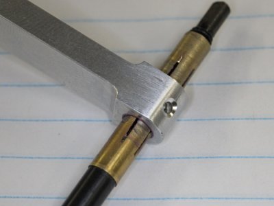
The axles are hollow drilled then I did the torch hardening & oil quench. Tempering was done in the mini oven at 450F & they turn out this straw color. They just run in the aluminum rod ends as per design. I don't think there is enough material left to run bronze bushings strength wise.
The axles are hollow drilled then I did the torch hardening & oil quench. Tempering was done in the mini oven at 450F & they turn out this straw color. They just run in the aluminum rod ends as per design. I don't think there is enough material left to run bronze bushings strength wise.
Attachments
Last edited:

