@RobinHood @Dabbler thank you so much for the valuable insight!
This is the kinematic setup I created in fusion360 to try and understand the root cause of the issue(if it's indeed a significant one).
The blue and green components are the sides of the dovetail(of course for simplicity I modelled the blue side as a 90deg dovetail aka just a flat surface, the green side was modelled with a 60deg angle so I get a better understanding of the compound angle when the lifting occurs). The orange component is the tapered gib. The lift movement I'm getting is represented by a revolute joint that allows mating faces of the orange gib to freely rotate on the respective faces of the blue and green dovetails. If I ground the green and blue components so they can't move in a any direction, there is no way for me to rotate the gib despite the fact that it's not constrained in motion by anything above or below it. So below is the ideal state: the gib is perfectly fitted to match both dovetails on either side.
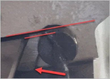
The only way for the gib to lift is for either on of its mating faces to have the wrong angle(or not be perfectly flat) or the the same with either side of the dovetails.
Shown below is the gib lifting up(or down depending on how you look at it), and this is only possible if the blue "dovetail" is not 90deg to the ground plane in this case since the green dovetail is fixed flat to the ground. Therefore if we assume the casting dovetails are perfectly flat, the only way for the gib to lift would be that it doesn't have full contact on both sides, so either the static side is not flat or has the wrong taper angle, or the sliding side is not flat or has the wrong taper angle.
@RobinHood understanding that the gib is allowed to move in my case because it's not tall enough, the above leads me to conclude that the root cause of the lift/slop is that it's not flat or taper angle is slightly off. Even if I shim it from above and stop is from lifting, it would still not be making full contact and therefore causing the excessive slop that I reported in the beginning of this thread despite being pushed far enough to make the motion in Y tighter than it needs to be. Does this logic make sense? Did I misunderstand your shimming suggestion?
In the case of the X axis, I do not need to push the gib in as much to remove the slop in the table. I understand that it's a longer gib and therefore would have more friction even if it's not perfect but I was able to reduce the slop in X and get smooth/easy movement on the wheel but not on Y.


