• Scam Alert. Members are reminded to NOT send money to buy anything. Don't buy things remote and have it shipped - go get it yourself, pay in person, and take your equipment with you. Scammers have burned people on this forum. Urgency, secrecy, excuses, selling for friend, newish members, FUD, are RED FLAGS. A video conference call is not adequate assurance. Face to face interactions are required. Please report suspicions to the forum admins. Stay Safe - anyone can get scammed.

Dirt Cheap Automatic Tailstock Feed for Your Metal Lathe

One time I had a 30" rifle barrel that i wanted to drill out to install a new rifled barrel insert, a common gunsmith job. They all use hand drills to do the job ... but, me being a farmer thought hell there has to be a better way. I rigged up a simple catch-hook that would catch the front of the cross slide and clamped to the tailstock, when the powerfeed was engaged the tailstock was just dragged along at the same rate...worked wonderfully for the first 15 inches of drilling.
This barrel (1890's vintage steel) already had a .375 (38-55) hole in it and I had to increase to .625....should be a simple drill operation shouldn't it! Just drill an inch or so, unhook and pull out to clean the flutes and run in, hook up again for another inch...It was until the mid part of the job...that drill bit jammed up and broke off with 2/3rd of the flutes stuck in the barrel. With that damn bit chucked to the tailstock, I couldnt feel the drag increase the way I would have had I been using the tried& true way of using a hand drill.
That little operation in "knowledge gain "cost me several hundred dollars to (and very lucky to do so) find a comparable vintage barrel to replace the buggered one.
If you don't mind my asking where do you buy your barrel liners
 
Since ITAR (International traffic in Arms Regulations) became a thing after 9-11, affordable barrel liners have become almost unobtainable up here. I used to get them from a shop in Kentucky that would ship them as "internal threaded pipe" but BATF slapped their PP, threatened them with a $250,000 fine....they lost interest in shipping to Canada.
There are a couple of barrel makers in Canada (Ron Smith, Torrington Ab. Bob Jury Red Deer Ab.) that will make one but they are expensive. They make a barrel blank (1.25 dia) same as for any barrel and then cut it down to barrel liner O.D. Because of the heat generated in the turning process, they all need to be stress relieved and because of the slim walls, some are accurate some aren't...like a box of chocolates you never know what your getting.
 
K.S.Arms in Edm. too. I Was seeking RF liners I'll have to whittle a donor I guess. i ran into a mdl 14 1/2 figured I'd hand it to a pal for his grandson. On a side note I ordered a dvd on bolt epoxying and lapping from Brownells which they cancelled but are sending the rest of the order because the State Dept. insisted on a $280 USD export permit for the dvd.
 
Gospel the $280usd is the application fee for them to consider it, but not a guaranteed export permit. You know I think it just spurs us on to find our own solutions I suppose i was only looking for "easy info" instead off doing my own R&D.
 
Rim fire .22 are a snap to re-line...drill & securely epoxy the liner in so it wont "walk out" during use...but because of pressures involved, center fire is a completely different cat to scratch.
Two reasons actually, pressure & heat generation. A .22 LR will typically only produce pressures under 12,000 psi ( .22 mag and the new 17's might be more but I have never researched them) .22 liners & epoxy will easily withstand those pressures even at the chamber, and you would have to shoot hundreds of rounds in immediate succession to generate enough heat to soften the epoxy.

Re-lining a center fire, even a BPCR requires a much more involved method or disappointment will surely be involved. Chamber pressures for BP start at 18,000 psi and can reach up to 28,000 in the larger Buffalo cartridges, Smokeless powder loads can start at the 18,000 level as well but can easily reach 55,000. Quite simply you cannot simply drill to slip-in fit & epoxy a liner in at these pressures. These pressures, at firing will expand a slip fit liner to be a very tight fit and stay that way...you have a bulge in the chamber that the brass swells to, and requires a ramrod to remove.
Old barrels needing re-lined for center fire need to be drilled in two stages. The chamber area and 2 inches ahead of it absolutely needs to be drilled (preferably reamed) to a very tight "pound in friction fit" or your chamber will be ruined on the first round fired. The rest of the barrel can be drilled a "slip in friction fit & epoxied" for ease of liner install before the epoxy sets up.
Make sure you order a liner in excess length of your barrel as the "pound in friction fitting" may damage a short piece of the liner. I leave about 4 inches longer (so about 8 inches in total to include chamber & throat) than needed sticking out of the bore end and use a piece of 4x4 hard wood block between the hammer (the biggest ball peen hammer you can find) and liner.
Many a rifle that has lasted a lifetime for an ancestor will last another lifetime for a new family member.
 
All good stuff Thanks
that Stevens 14 1/2 doesn't have a centered bore in the barrel about 3/16" high at breech and center at muzzle as I don't doubt you know.
I've read that most rf liners are button rifled hmm Do you think turning down a donor barrel and threading it 40tpi would be a good substitute to epoxy in?
I love BPCR 45-70 45 colt both paper patched smokeless hurts too much Ha No such thing as a long colt just a short 45 s&w
My email is [email protected] if your so inclined
 
ahh I see says the blind man. I was thinking pump action 14 1/2 Remington which is a center fire (44 WCF I have held and shot).

I have never held a Stevens 14 1/2 and am interested in your Off center comment. Is this how they used a center fire action/falling block for a rim fire cartridge.
Just a comment on off-set bores. It is very common for barrel blanks to come out of a gun drill with the bore very off-set from center at the drill exit end, actually is is very unusual for bores at both ends to be within 10 or 20 thou of center. I have seen barrel blanks from reputable Stateside manuf. delivered through Brownells with exit end more than .250 off-set. After center to center contouring, nobody knows how badly the barrel looked on their $5000 custom gun beforehand....they all shoot the same.
 
I'll Send some pic's as to the why of it shrugging going on
it is a rolling blk just a pipsqueak it even takes down by a knurled thumb bolt thru the recvr. just right for a little guy to shoot with his Gramps
 
Rim fire liners are made from tubing that is rifled. 5/16 tubing was what Redman used for their liners. I installed dozens of them years ago. The Parker Hale liners that Ron Smith used to use were a different diameter as I recall.
 
This thread has been a very interesting read for me. I'd like to add just a few comments.

As @historicalarms has said, barrels often end up drilled off center. Although I've never seen one that is 1/4" off - Holy Moses!!! Maybe it was before the barrel maker cut the barrel contour though. I've also never seen one that was straight. Not ONE! Every single one I've ever seen has had a bit of an arc to the axis. That's why I prefer to chamber through the headstock with a spider on both sides of the head to deliberately offset the back end and precision align the working end such that the axis of the end I'm working on (muzzle or chamber) is truly concentric to the spindle axis. Others may use other methods successfully, but mine works for me at competition worthy levels.

As @Dabbler has said, all my chambering end work has been done with precision fit (+/- 0.0001 yes a tenth of a thou) bushings to guide the finish or roughing reamer or drill in the bore on the lands with a floating reamer holder. I let the Bushing establish the course.

Although I absolutely love the creativity of the idea itself that was first pointed out by @YYCHM, I could never imagine doing any chamber work using that method.

@Brent H posits that it's only 3", but for my chambering work, I take his point to the extreme. Depending on the steel and chamber size, I usually cut just 25 thou at a time at the slowest speed I have, then pull the reamer out, clean, relube, and repeat. I also always hold the reamer holder in my left hand while I rotate the tailstock quill advance so I can feel the reamer cutting and thereby have a good feel for what is happening in there. It's a lot of repetition and it's very slow going, but my results speak for themselves.

I really do want to thank @YYCHM for showing us the idea. I may never use it, but I am always fond of growing my Basket of Tricks and my how-to knowledge base.

I love this forum.
 
I'm late to the party. I get that the tool post in original link is kind of old school. But why drag the tailstock along for the ride? Isn't that what toolholder chucks are all about - drilling under carriage power?

1623904988265.webp
 
T.. all my chambering end work has been done with precision fit (+/- 0.0001 yes a tenth of a thou) bushings to guide the finish or roughing reamer or drill in the bore on the lands with a floating reamer holder. I let the Bushing establish the course.

Do you have a pic of this setup? I'm interested for ulterior motives.
 
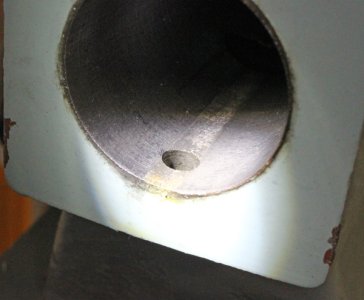
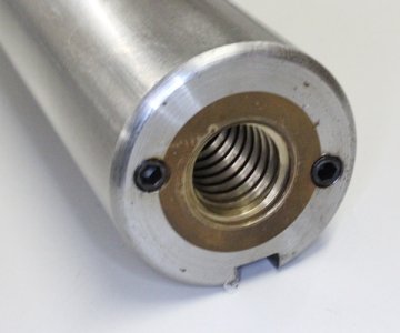
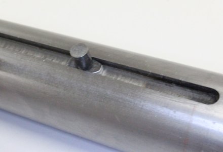
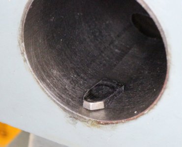
Hmm.. YOUR lathe maybe LoL. I've often wondered about the teeny key/pin in my 14x40 TS. Is it more of a cheesy alignment device for the quill or is it intentionally small & intended to shear? The casting itself looks sufficiently robust but the key is the weakest link. I know that its hardened though so I'm not so certain its intended to shear. I got thinking about this because I want to make a longer shoe that fits better to the slot width. Seems like whenever I had a jam drill issue, the shank spins in MT socket... usually followed my cuss words.

So how do those guys drag the TS? Do they semi tighten the clamp so it cant lift? Now the powerfeed is seeing that drag force on top of drilling? My lathe has the Vee on one (opposite) side, so isn't chuck reaction force wanting to rotate TS - thus potentially lift it off the Vee? What am I missing?
 

Attachments

  • IMG_1765_edited-1.jpg
    IMG_1765_edited-1.jpg
    31.5 KB · Views: 2
  • IMG_1769_edited-1.jpg
    IMG_1769_edited-1.jpg
    28.7 KB · Views: 2
  • IMG_1771_edited-1.jpg
    IMG_1771_edited-1.jpg
    20.9 KB · Views: 2
  • IMG_1776_edited-1.jpg
    IMG_1776_edited-1.jpg
    34.5 KB · Views: 2
@PeterT You use a drag link with the quill locked, so theforce pushes through the locking device to the drill. There should be no pressure on the key. (my 12" has a 1" long key FYI)
 
Do you have a pic of this setup? I'm interested for ulterior motives.

Unfortunately, no I don't. I have another shop project taking priority right now. Maybe I can jury rig something up later this week to take photos for you.

I assume you are wondering about the setup and not the reaming process.

Basically, I made spiders for both ends of my lathe. Most will wonder why I made a spider on the business end when you could use a four jaw. The problem with a four jaw is that the bearing surface of a four jaw is too long and the jaws want to align the work on their axis. You do not want this. You want the bore to be absolutely perfectly aligned with the Spindle axis. Only a point contact allows this. I use round brass buttons on the spider bolts to protect the work and allow it to pivot.

If you don't do this kind of work a lot, you could also wrap the work once with a copper wire to allow the work to pivot in a four jaw. That's what I did until I decided it was just easier to make a front spider. In fact, I ended up making a spider out of a dedicated backplate.

The working end is centered using a long 10ths indicator positioned down inside the bore AT THE SAME LOCATION as the front spider. This ensures that the bore is centered, but not necessarily aligned axially. The bore is aligned axially to the Spindle bore using the rear spider to move the other end until the indicator does not move as it is moved in and out of the bore at a location OTHER THAN where the front spider is. The process is repeated over and over and over until the indicator DOES NOT MOVE AT ALL in any location deep or shallow. This is critical. Long indicator needles typically reduce the accuracy of the indicator by the ratio of the needle length. But it's easy to see a quarter of a tenth or even less on the dial.

There are other ways to do this too such as using a ground fitted bushed indicator rod in the bore and measuring the rod wobble. I don't like this method because it depends too much on the fit of the rod. A better alternative is to mount a long indicator rod in the tail stock that can float in the bore. One can hang a weight on the rod so the wobble end always rests on the bottom of the bore, and then eliminate the wobble at all locations in the bore.

I don't like the ground rod method because it depends too much on the perfection of the fit and grinding. The long floating rod works just fine because the fit and grinding don't need to be perfect. But I prefer the long indicator method simply because it's faster and easier. I have compared the long indicator and floating rod methods and didn't find a difference.

Let me know if that didn't paint a picture in your mind.
 
Susquatch I kind of get it but I’m missing the gripping part if conventional Chuck or collet is replaced by something else, the inboard bed side spider maybe? Then you indicate part on both sides of head stock? I don’t have any experience with the parts you are making so probably why I’m confused. No rush if it’s convenient one day snap a pic or scribble a sketch. I’m thinking forward to model engine cylinder liners like my radial where there are sequential machining ops & consistency is important.
 
My lathe has the Vee on one (opposite) side, so isn't chuck reaction force wanting to rotate TS - thus potentially lift it off the Vee?

A drilling operation produces what is known as a “couple” as far as rotational forces on the TS. The rotational force has no moment arm w.r.t. the TS body; thus it does not have a tendency to lift it. The weight of the TS, how it sits on the flat and in the Vee is plenty strong enough to resist but the largest of forces. Sure, you can set the TS position lock to a slight drag as well. Improves the rigidity of the setup.

In the formula below, d would be the distance between forces F and F1 on the cutting edges of the of the drill.

From “Mechanics for Engineers”, Statics and Dynamics, 3rd Ed, pg 66
image.jpg


Things start to get very interesting if the drill or work were to bend.... now you DO have a moment arm acting on the TS and it will lift it. Same thing is true if you only have one cutting edge of a drill doing all the work or when one cutting edge breaks through the work first at the far end. I think we have all experienced that moment...
 
Back
Top