• Scam Alert. Members are reminded to NOT send money to buy anything. Don't buy things remote and have it shipped - go get it yourself, pay in person, and take your equipment with you. Scammers have burned people on this forum. Urgency, secrecy, excuses, selling for friend, newish members, FUD, are RED FLAGS. A video conference call is not adequate assurance. Face to face interactions are required. Please report suspicions to the forum admins. Stay Safe - anyone can get scammed.

4140 crankshaft modifications - propeller hub build

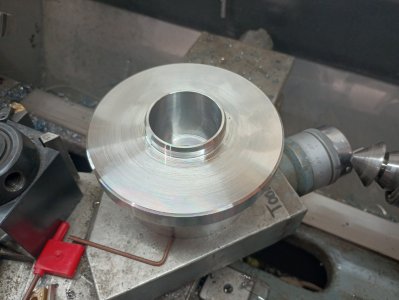
do you guys think i should take a bigger bite ?
I’d give it a try during the roughing phase. Also try a faster feed rate. I usually go to the point where the chips just turn from straw to blue (straw when they are airborne, [light] blue once they have landed). The lathe will let you know if it is still happy. 4000 series steels like relatively big bites for good surface finishes. Also prevents work hardening which can be a problem with light cuts.

Are you planning on finishing the dimensions (at least both faces) once the flange is mated to the new crank?

You going to use the “BBQ & freezer” method to get the flange onto the crank?
I am no expert, but ill do the same, as I come close to final dimensions ill swap to a DCGT or CCGT insert meant for aluminum and take some fine cuts with a fast sfm/rpm. Finish is normally spectacular and can easily take a .001" on 40X series stock. Or a shear tool of you prefer HSS.

Gluck
 
I’d give it a try during the roughing phase. Also try a faster feed rate. I usually go to the point where the chips just turn from straw to blue (straw when they are airborne, [light] blue once they have landed). The lathe will let you know if it is still happy. 4000 series steels like relatively big bites for good surface finishes. Also prevents work hardening which can be a problem with light cuts.

Are you planning on finishing the dimensions (at least both faces) once the flange is mated to the new crank?

You going to use the “BBQ & freezer” method to get the flange onto the crank?
yea i was thinking of trying the bigger cuts for the roughing, i still have over 1.5" of diameter to clear out on that side, surface finish has been pretty good with the .03/.04 cuts

i was going to do the toaster oven and freezer method, as i have a toaster oven in the garage for powder coating, and other non food type things

i was thinking of leaving the flange face .01 big for a final squaring after mounting, i just need to figure a good way to chuck it up as i dont have a steady. i may be able to use the 4jaw live center i have in the front bolt hole with a boring bar, or i may have to actually make a steady

I am no expert, but ill do the same, as I come close to final dimensions ill swap to a DCGT or CCGT insert meant for aluminum and take some fine cuts with a fast sfm/rpm. Finish is normally spectacular and can easily take a .001" on 40X series stock. Or a shear tool of you prefer HSS.

Gluck

i was thinking of trying this trick, i have to look through my collection of inserts to see if any of them are ment for aluminum, it would make doing the internal bore much easier if i could take the final .001 or .002 instead of having to make it to the final dimension with a big cut on a boring bar

really its that bore thats the most critical thing, im hoping that the 5/8's bars i have are up to the task
 
Ill gladly whip you down some of my inserts, Just have to wait for canadapost!

As for the freezer method, Forget it, Go to your local linde ( praxair ) location and ask for 1 lb of dry ice, some times its free, some times a couple bucks, or a coffee for the boys! I go so often, I now ask for a scoop of raisins ( like raisin bran )
Make friends - the fallowing visit it will be free!

Gluck
 
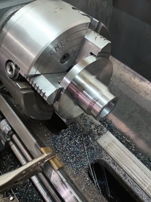
little bit of progress today, i had other things to do so i only got in an hour or two

flipped it and did the work on the face, the surface finish on the face isnt great, but its better in person than what it looks like on the photo

the 5/8 bar seems to do ok, i already have some aluminum inserts on the way, i had to order a 6mm keyway broach anyhow, but thanks for the offer @Proxule

next up i will have to chuck it back up and finish turning down the body and the interference bore


IMG_20240929_172706818_HDR.jpg
 
Well with .004 to go, I dialed in a .001 doc, finish the rest of with paper, went in,stopped went out.......

Dam thing is .003 oversized, my .001 doc took off .007 on the radious...wtf

Not sure if I should weld the bore or add or this to the scrap pile, or just go cry over in the corner

IMG_20241014_143151867.jpgIMG_20241014_143140795.jpg
 
Last edited:
Well with .004 to go, I dialed in a .001 doc, finish the rest of with paper, went in,stopped went out.......

Dam thing is .003 oversized, my .001 doc took off .007 on the radious...wtf

Not sure if I should weld the bore or add or this to the scrap pile, or just go cry over in the corner

View attachment 52872View attachment 52873
F*********k
Is the word you were after.


I would add to this. Vs. Add to the bore. Hard to dial in a cut a bore to specs. At least I always find it harder. Weld it up snd try again or scrap it.

No harm. I mean its all good practice lol.

I like to shove my compound over 3 degrees swung from the z axis will give you .0001 on diameter for every .001 travel on the compound slide.

Gluck!
 
i dont know if i should weld it up with the chances of cracks forming in the haz, it would be a radial crack and could separate the whole propeller from the crank, i have no way to anneal it before putting into service, and given its 4340 and not just 1018 i think the chances are high

i used a dial indicator on the tool post, as well as a the dial on the machine, so im not sure if the insert decided to grab more and flex the bar, or if the running the tool out caused it to grab and cut more, or if it was just that tiny amount of cut is not possible with carbide, i really dont know, im just wishing at this point i did the last few thou with paper

i ordered a 11" chunk of 5" round 6061 t6, there are more than a few aluminum prop hubs floating around, and that will give me enough to screw up 3 more times...it will also be a lot quicker to machine up
Sigh, Sorry!
Yeah fair enough I don't know enough about 4X series welding, The HAZ is indeed something to consider, Although if you could anneal it :D
No one in Calgary with one of those mini ovens to hold the temp for you?

Would make for a fun ride if the propeller separated from the crank, Like free gliding. Weeeeeeee

I do like the aluminum idea, 3x practice, makes the 4th perfect? !

Keep us updated!

yea i dont either, and im a welder! but doing a bit of research it seems like it may not be a great idea

you have to anneal it at like 1600! im sure i could find someone with the equipment, but i doubt it would be free, and more likely cost more than the billet (5" dia x 11" long was 120 + shipping...i added a few more items to make it worth the 40$ of shipping)

haha well im hoping i get it right the first time this time! then ill have a nice chunk of 6061 for something else...

does anyone know how much the interference fit needs to be for aluminum ? its a 1.4" shaft, .001-.002 for steel, but aluminum ? .003-.006 ??
 
@phaxtris I assume we talking about the bore that ended up oversize?
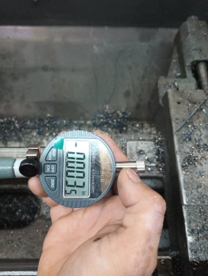
- what are you using for bore measurement?
- do you lock the cross slide every new DOC pass?
- do you take the same spring pass count as you converge to dimension?
- did you attempt to equalize the last couple DOC passes or saved the last thou for a finish cut?
- do you change the feed between spring passes?

Re dial gage, that's what I used pre-DRO so using that & not trusting your dials was a very good idea. But what I discovered is that some of the digitals don't respond as well while the machine is running. For demo, if you put a sensitive analog DTI (like tenths reading) and mount it very solid, you can see the needle float +/- a mean number. Heavier gages (aside from being coarser reading) weigh more & can be subject to variations. Mag stands (the arms, the joints, the locking mechanisms to dial back) can allow movement or even drift under normal machine vibrations. This doesn't explain a 0.007" oops, but it could be a collection of any of these small things going in the same unfortunate direction. We have all been there. Another factor is part temperature from machining, but usually that makes for undersize OD's.
 
^ This. Nice summary of the issues that bite us @PeterT.

Also, maybe the op mentioned his cutting tool design (hss, carbide, insert, etc) but these tools all add differences to the way final dimensions are best approached.

Of all the issues Peter described, that last final dial-in spring pass is the one that bites me the most often and perhaps it warrants a little more discussion.

Tooling and the part are BOTH flexible. A heavy cut prior to a spring pass will often leave more pressure on the tool than can be reliably dialed out on the tool. I've even had to dial out instead of in to get the right skim. The preferred way to do this is to make that last pass the same depth as the one before it. You cannot reliably cut 30 thou, 30 thou, 30 thou, and then 1 thou. Better to cut 30, 30, & 31. Or 30, 30, 15, 16. The second last pass (the 15) has to be carefully measured before and after cuz it prolly won't be 15. It will likely be 13,14, 16 or 17 so the last cut will have to be 17, 16, 15 or 14. Hopefully that's clear. At any rate, it's a skill that should be learned.
 
i ordered a 11" chunk of 5" round 6061 t6, there are more than a few aluminum prop hubs floating around, and that will give me enough to screw up 3 more times...it will also be a lot quicker to machine up
That was the right decision. Don't take those kind of chances. I would use the f*ckup you have to practice with, and experiment to see how to arrive at a finished dimension of your choosing, so the next hub comes out perfect.
 
last couple passes same feed rate, both very small doc, using a bore gauge set with a mic from the crank, alum wnmg 04 nose rad, 5/8 boring bar ~2" extended, no cross slide lock, mechanical indicator on the cross slide (digital is on the bore gauge), the dial and the indicator indicated what should have been the same doc

the only thing that was done differently was i power fed in and power fed out without moving the tool in the event i would need to go back in, so either the infeed or the outfeed something grabbed and pulled the tool in

should have just taken off the last few with paper, i was concerned it would not be consistent or parallel

@YotaBota i can fit the crank, shes loosy goosy, the interference fit of the part is .800" long, there is nothing to remove unfortunately

i like @Ironman 's idea of milling out the hub a few more times with some random chosen dimension, find out why, or what i need to to differently to hit that dimension exactly

i probably wont get much done with it this week/weekend, its shaping up to be pretty busy for the next few days over here
 
If I had to guess, and I could be very wrong, when you dialed in your final depth of cut that should have brought you to final dimension. But you fed it out as well without moving the tool away from the work taking a spring pass on the way out. I am just an amateur and this is just a guess and is probably not even worth the usual 2 cents.
 
If I had to guess, and I could be very wrong, when you dialed in your final depth of cut that should have brought you to final dimension. But you fed it out as well without moving the tool away from the work taking a spring pass on the way out. I am just an amateur and this is just a guess and is probably not even worth the usual 2 cents.

It's valid, it's on the list of possibilities for sure
 
I only power feed in one direction, back off the tool, spin out reset & repeat. Or more commonly with table locked, stop the lathe & hand feed out. But I don't really have a good technical reason as to why. Maybe comes from an ancient bad experience of power feeding ACCROSS with the wrong lever selection haha. But thinking about this some more, particularly without having a table lock, it could be a contributing factor if it loads the tool assembly differently based on in-feed vs out-feed direction. But mostly I cant think of any advantage PF in & out offers for finishing to dimension. In roughing I guess you save time by incrementing DOC each pass, but finishing mode is 100% focus on hitting the target & finish and time is whatever it takes because it will be shorter than making a new part.

One thing I do as a spot check as I get close: PF in at whatever the likely finish DOC will be, stop machine, hold the DOC setting & back out. Now if you see any hint of scribe line along the surface, its telling you the boring bar is still loaded & requires spring pass(s) to relieve. Sometimes you will see some line near the mouth but not deeper in the bore. This is a function of material deflection under load, different issue that cutting tool deflection. But an important thing to do at this point IMO is change the feed, ideally from coarse to finer. Why? Because you don't want to be 'threading the same groove' in your spring pass, which is not materially affecting the mean bore dimension. You want to be planing off the hill tops from preceding pass & the only way to do that is changing feed setting (or do it manually which is even more random & what I do on short depths like bearing seats). So if you have a sense the material requires 3 spring passes, you hold the same DOC setting but run each pass at progressive finer feeds. Its more work but its also more consistent.

But lack of table lock is unfortunately the root of much evil. It shows up in many forms; chasing your tail on dimensions, variable finish, tool chatter on higher loading modes like parting, allows higher wear rate to feed screw & nut.... I'm not suggesting go out & violate your machine without a bit of research & thoroughly thinking it through. My Taiwan machine is basically a glorified knurled knob set screw that pushes against the gib strip & locks the table that way. But many lathes have a setup that doesn't lend itself to this (gib on left side close to the rotating hand muncher for example). But something to think about particularly if you ever do go to DRO, the scale position may have to work around this in any event.

The other sanity check thing you can do today is set up your dial gage the way you had it & pull on the tool post laterally back & forth. What does the needle deflection say? As the machine wears, particularly lead screw / nut assembly, you may have to back the dial out a healthy amount & dial into new target DOC setting removing as much backlash as possible. This is considered good practice in any event but might become necessity with finishing.
 
Back
Top