• Scam Alert. Members are reminded to NOT send money to buy anything. Don't buy things remote and have it shipped - go get it yourself, pay in person, and take your equipment with you. Scammers have burned people on this forum. Urgency, secrecy, excuses, selling for friend, newish members, FUD, are RED FLAGS. A video conference call is not adequate assurance. Face to face interactions are required. Please report suspicions to the forum admins. Stay Safe - anyone can get scammed.

Weiss VM32 CNC Conversion

David,
Yes, across pin 7 & 9 (The Cathode (banded side), to the + side pin 9)

The diode is connected reverse bias so current only flows through the diode for a few ms whenever the relay drops out, otherwise it's as if it's not there. So instead of the voltage building up to a damaging spike, as soon as it gets to about 0.7V, the diode conducts and dissipates the energy from the collapsing field back into the relay coil. Almost any diode would do, say a 1n4007 or whatever you have on hand. Any diode with say a 100V or greater rating and 1A or so. I would not activate that output until you install the diode, your playing with fire.
Gonna need some hand-holding here...
I have no diodes on hand because that would infer that I have a clue what I'm doing :D

Like this?
 
This is your flyback diode. It protects the driver transistor beside it.

1734638900727.png
 
David,

Sorry I forgot about the relay module, I was thinking just a relay. Yes that board already has a FWD.

False alarm;-)
 
The only place a diode might be handy is across the brake solenoid winding inside the motor. If it isn't already there as an internal part of the brake setup. It would suppress arcing across the relay contacts and reduce electrical noise for your electronics control system.

I'll do you up some sketches in a moment.
 
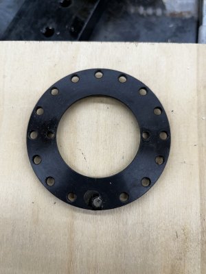
I’d like to use this drilled disk with an optical reader to make an encoder for the mill spindle.
The ring has 16 holes. I’m wondering if that’s sufficient resolution?
IMG_1972.jpeg
I don't really want to use a rotary encoder like this as it will interfere with my eventual pneumatic drawbar.
1734738443209.png
 
Options, options, so many options.........
A couple to consider:
1) 3D print disk with many slots or holes
2) To avoid the power drawbar, use the rotary encoder linked to the motor pulley and just do the ratio conversion in software.
 
I don't really want to use a rotary encoder like this as it will interfere with my eventual pneumatic drawbar.

This is a mill not a lathe. I don't think you have to sync spindle position with anything else unless you want to do really fancy stuff like synchronized milling on a spinning workpiece.

All you really need is rpm and not even really precise rpm.

Looking at it the other way, mills don't change speed much in any one given revolution, so simple rpm measurement is more than adequate.

Just an opinion David. Hope it helps you decide.
I think rigid tapping requires the index pulse so it knows when to start. But I don't know that for sure.
 
This is a mill not a lathe. I don't think you have to sync spindle position with anything else unless you want to do really fancy stuff like synchronized milling on a spinning workpiece.

All you really need is rpm and not even really precise rpm.

Looking at it the other way, mills don't change speed much in any one given revolution, so simple rpm measurement is more than adequate.

Just an opinion David. Hope it helps you decide.
Rigid tapping on a CNC mill requires that the machine spindle rotation and feed rate match the thread pitch. This eliminates the need for a floating tap holder which would otherwise take up the Z axis ‘slack’ if the feed rate doesn’t match the thread pitch.
 
Rigid tapping on a CNC mill requires that the machine spindle rotation and feed rate match the thread pitch. This eliminates the need for a floating tap holder which would otherwise take up the Z axis ‘slack’ if the feed rate doesn’t match the thread pitch.

Didn't know that you were planning to do thread milling. Changes my opinion totally. Now you need to coordinate Z travel with spindle rotation.

Now I'm not sure your sensor array has enough resolution! I suppose if the processor is fast enough, it can interpolate between pulses, but it would better to have enough pulses to fully discern your smallest thread pitch.

Anyways, sorry for the interruption. Carry on! I'll go back to sleep now.
My CNC controller doesn’t handle the G-code required for rigid tapping so thread milling is my only option for threading.
 
Back
Top