Yeah you don't want me to try. I seem to keep mucking things up. Paul's turn...Thanks Paul. I will have to as there's no way I can do it unless I break out the angle grinder!
-
Scam Alert. Members are reminded to NOT send money to buy anything. Don't buy things remote and have it shipped - go get it yourself, pay in person, and take your equipment with you. Scammers have burned people on this forum. Urgency, secrecy, excuses, selling for friend, newish members, FUD, are RED FLAGS. A video conference call is not adequate assurance. Face to face interactions are required. Please report suspicions to the forum admins. Stay Safe - anyone can get scammed.
You are using an out of date browser. It may not display this or other websites correctly.
You should upgrade or use an alternative browser.
You should upgrade or use an alternative browser.
Weiss VM32 CNC Conversion
- Thread starter David
- Start date
That's why I still have the hand cranks.I seem to keep mucking things up.
More progress today. Basically have to disassemble the mill to install the ball screws.
First I made a drill guide to shift the mount holes in the casting.
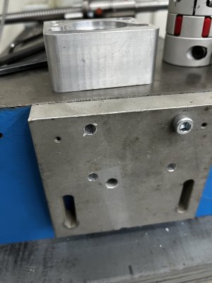
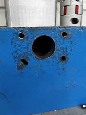
That worked out well so I turned my attention to taking the head and the column off so I could install the Y and Z axis ball screws.
I don’t have pics of this as it was very difficult to do.
There’s a gas strut in the column which was a complete pain in the rear to remove because unlike gas struts on a trunk for example, the strut couldn’t be popped off the ball. So I had lean the column back so I could unscrew the lower ball about 1/16 of a turn at a time for the length of the 1” stud.
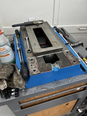
Once off I tried to slide the Y axis ball screw into place.
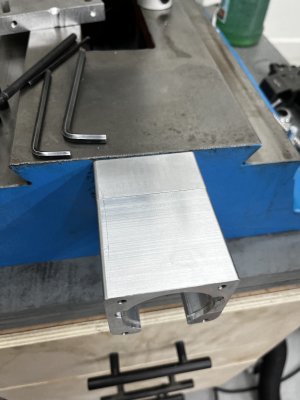
No dice as the base casting prevented the end from going all the way through the hole in the front of the base.
Break on the angle grinder and cut the opening an inch longer.
Dressed the new cut with a file and now the ball screw can slide into place.
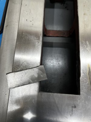
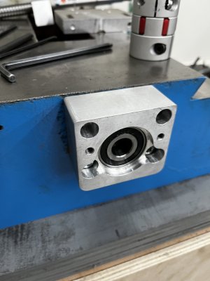
With the ball screw in place I put on the mount which contains two bearings for the driven end of the ball screw.
Mount fits perfectly on the shaft but the hole in the front of the casting isn’t large enough for the ball screw to drop down enough for the mount to match my up with my newly drill holes in the casting.
Off to Home Depot to buy a 1.25” hole saw to enlarge the hole.
With the hole enlarged it was easy to put everything together.
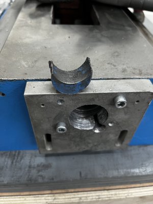
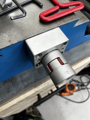
First I made a drill guide to shift the mount holes in the casting.


That worked out well so I turned my attention to taking the head and the column off so I could install the Y and Z axis ball screws.
I don’t have pics of this as it was very difficult to do.
There’s a gas strut in the column which was a complete pain in the rear to remove because unlike gas struts on a trunk for example, the strut couldn’t be popped off the ball. So I had lean the column back so I could unscrew the lower ball about 1/16 of a turn at a time for the length of the 1” stud.

Once off I tried to slide the Y axis ball screw into place.
No dice as the base casting prevented the end from going all the way through the hole in the front of the base.
Break on the angle grinder and cut the opening an inch longer.
Dressed the new cut with a file and now the ball screw can slide into place.

With the ball screw in place I put on the mount which contains two bearings for the driven end of the ball screw.
Mount fits perfectly on the shaft but the hole in the front of the casting isn’t large enough for the ball screw to drop down enough for the mount to match my up with my newly drill holes in the casting.
Off to Home Depot to buy a 1.25” hole saw to enlarge the hole.
With the hole enlarged it was easy to put everything together.


Attachments
Last edited:
On the Seig X3 mill it is possible to drive the table past the limits if you do not have limit switches or if a switch was to fail. Not sure if this would be an issue on your mill.
Attachments
Oh I actually have a central oil pump that came with the kit I bought.View attachment 54938
Due to the high speed movements in the future, take your pick.
Curious though what's the advantage of one of these units over something like this?
More progress.
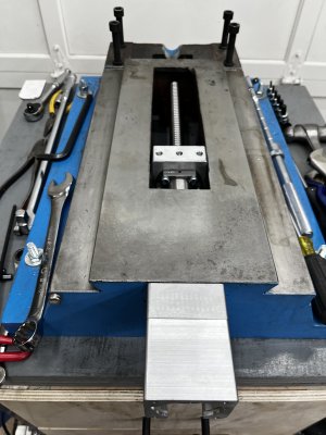
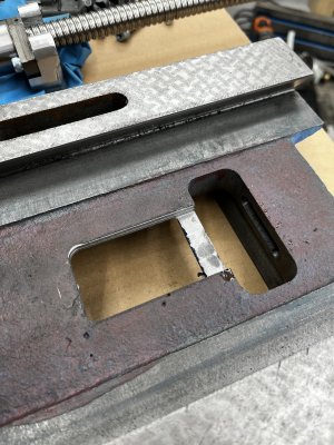
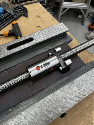
I needed to mill out a slot in the Y table for the x-axis ball nut.
Since my mill is in pieces, @PaulL came to the rescue.
His huge First mill makes mine look like a KitchenAid mixer! Very nice machine. I can see why there’s so much love for big machines.
Anywho, we got the slot milled out.
Double ball nut fits perfectly.
We had to mess around a bit with tooling to find something long enough to reach the slot so we could lengthen the slot for the M8 cap screws.
A counter bore makes a fine side mill if used carefully. Good thinking Paul.


Last edited:
The main challenge was standing the carriage up solidly:


Fortunately I had a 2-3-4 angle plate nice and square, and a second 2-3-4ish block I'd just finished squaring. Between the two we were able to sandwich the carriage between them and anchor it. We just had one poor moment in which the filling attempted to pull out of the sandwich, leading to a quick clamping change to move the right hand clamp over the dovetail edge and re-zero-finding the slot.
A productive morning, and a happy @DavidR8 . He can moderate the picture (and this sentence?) out of existence if he doesn't like it ;-)
Hoping folks can check my thinking.
The X axis ball screw that came in the kit I bought is too long for my table so I need to cut it down and machine the end.
I don't want to mess this up.
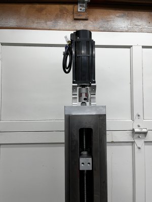
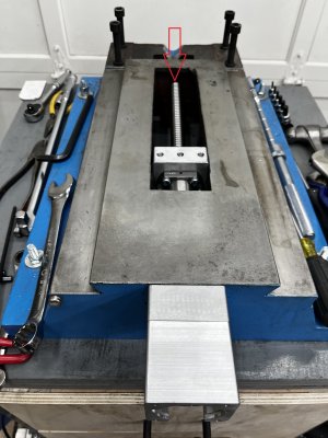
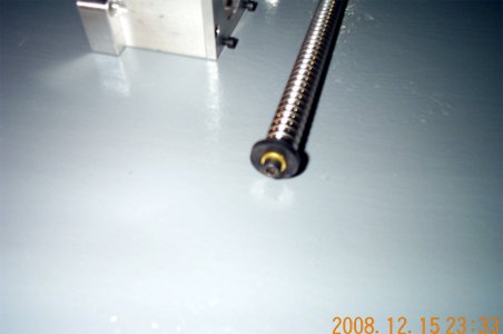
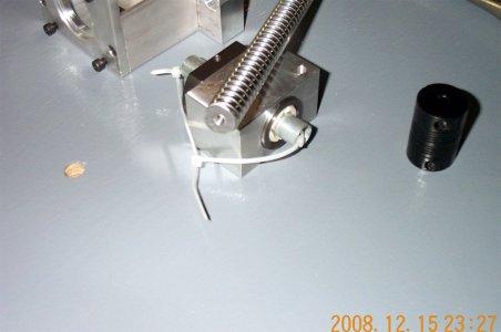
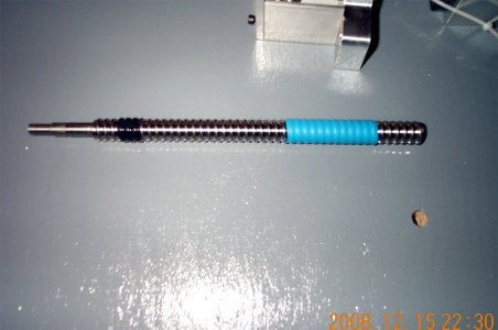
Here's some pics to illustrate the situation.
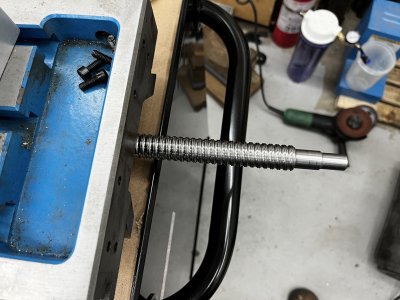
Here the excess length and the machined end.
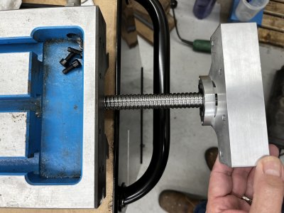
This is the bearing carrier and the mount that bolts onto the end of the table.
I measured the distance between the end of the table and the mount and came up with 130mm.
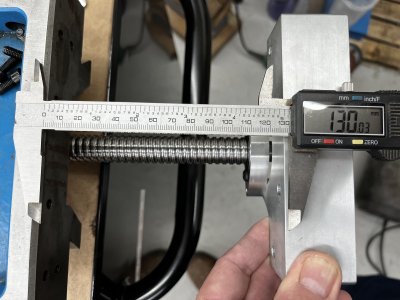
This is what 130mm looks like on the ball screw.
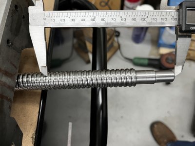
So my thinking is if I cut off 130mm of length then machine then machine the features on the end, the mount should bolt up to the table. For good measure I may make the bearing surface a smidge longer to make sure the mount seats well on the end of the table.
Is my thinking correct or am I overlooking something obvious?
The X axis ball screw that came in the kit I bought is too long for my table so I need to cut it down and machine the end.
I don't want to mess this up.
Here's some pics to illustrate the situation.
Here the excess length and the machined end.

This is the bearing carrier and the mount that bolts onto the end of the table.

I measured the distance between the end of the table and the mount and came up with 130mm.

This is what 130mm looks like on the ball screw.

So my thinking is if I cut off 130mm of length then machine then machine the features on the end, the mount should bolt up to the table. For good measure I may make the bearing surface a smidge longer to make sure the mount seats well on the end of the table.
Is my thinking correct or am I overlooking something obvious?
Last edited:
lucsimoneau
Well-Known Member
Most pre-machined ball screws have the other end machined with a snap ring groove, might be easier to machine the other end. The outer skin of the metal is hard but the interior is relatively softer. Have machined quite a few for our mini-mills.
Unfortunately, the other end end has a threaded end for a nut. So this end seems like the easier one to modify.Most pre-machined ball screws have the other end machined with a snap ring groove, might be easier to machine the other end. The outer skin of the metal is hard but the interior is relatively softer. Have machined quite a few for our mini-mills.
My plan was to heat the area where the cut needs to be made and back where the features need to be machined.It’s similar to machining IHC or chrome plated materials. That first cut ideally is such that you get ‘under’ the outer skin. In a pinch some grinding to get rid of the bulk of the hard stuff first may be easier if you have a small/light machine to do this with.

