-
Scam Alert. Members are reminded to NOT send money to buy anything. Don't buy things remote and have it shipped - go get it yourself, pay in person, and take your equipment with you. Scammers have burned people on this forum. Urgency, secrecy, excuses, selling for friend, newish members, FUD, are RED FLAGS. A video conference call is not adequate assurance. Face to face interactions are required. Please report suspicions to the forum admins. Stay Safe - anyone can get scammed.
You are using an out of date browser. It may not display this or other websites correctly.
You should upgrade or use an alternative browser.
You should upgrade or use an alternative browser.
Weiss VM32 CNC Conversion
- Thread starter David
- Start date
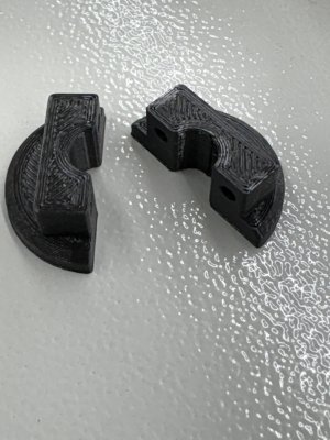
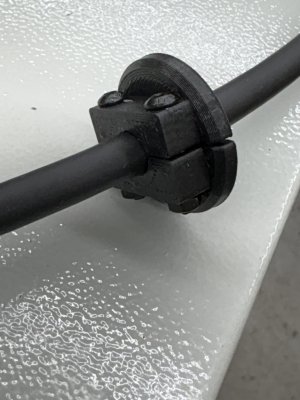
It’s definitely flexible as I 3D printed it. Also easy enough to design a new one with a cutout in it.Is the panel flexible at all? Can you slit it to the hole (cable size) them twist it open enough to slide the cable in? Maybe a little heat to help the twist.
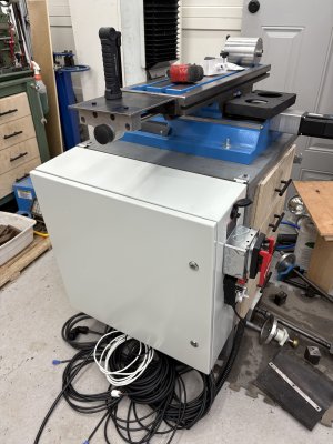
That's looks like a nice enclosure, is it metal?
It’s a Vevor enclosure. I think it was $150. Super impressed by it. Grounded and removable backplane, two locks and weatherstrip on the door. Definitely recommend if you need such a thing.
Last edited:
Pitter, patter, get at 'er!I've just got to get back on the ELS project for the lathe again...
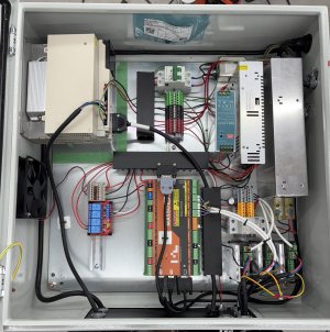
Electronics enclosure almost ready!
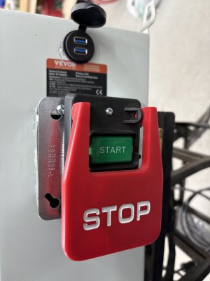
240V AC in, with breaker and emergency off switch.
48V DC for servo drives in.
24V for MASSO, relays and proximity switches in.
24V dedicated power for Z axis servo brake in.
External usb port in.
Need to run wires for 4-relay board to control brake, air solenoid and tbd.
Need to figure out proximity switch wiring still.
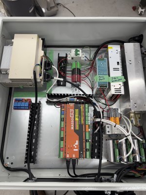


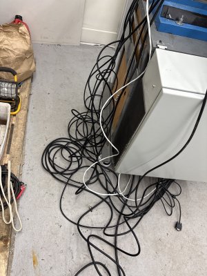
Red Green would have that cleaned up in no time. Nothing a roll of duct tape couldn't handle. lolCable management is required.
Progress
You any good at splicing.....
Another approach just a wee bit better than duct tape is a grocery bag full of wire loops hanging off the side with a, few chocolate bars on top to hide the spaghetti.
Hey, now there is an idea! Don't hide it! Put it right out there in plain sight, spray it ivory, put it in a bowl, and add tomatoe sauce!
I have a plan. Maybe not a great one but I have one.You any good at splicing.....
Another approach just a wee bit better than duct tape is a grocery bag full of wire loops hanging off the side with a, few chocolate bars on top to hide the spaghetti.
Hey, now there is an idea! Don't hide it! Put it right out there in plain sight, spray it ivory, put it in a bowl, and add tomatoe sauce!
Is this not the system that had the Bergerda drive?Except for proximity switches we’re all ready to go!
View attachment 59931
Yes it is. The Bergerda drive is in the upper left corner of the enclosure. I had to mount it to the side as it was too deep to be mounted on the back plane.Is this not the system that had the Bergerda drive?
Dan Dubeau
Ultra Member
Nice panel work!
Thanks Dan. I still have a bit of tidying to do and need to add more cable duct on the lower right side.Nice panel work!
I did manage to get movement late this afternoon. X axis jogs fine but the Y and Z are not quite right. And the spindle is not working so I need to figure that out as well.
Ah! Now I see it.Yes it is. The Bergerda drive is in the upper left corner of the enclosure. I had to mount it to the side as it was too deep to be mounted on the back plane.
Do you have a scope to see if the non working axis are getting pulses?
I think it's a coordinate issue. I was able to jog all axis but then they stopped for some reason. I'll dig more into it tomorrow.Ah! Now I see it.
Do you have a scope to see if the non working axis are getting pulses?
Sorted out some stuff this morning.
The non-running spindle? Well that was 100% user error. I forgot to plug in the cable from the controller to the drive.


Now the spindle goes from 1 RPM to 4000 RPM to1 RPM in the blink of an eye.
The axis issues were because I when I was bench testing everything I set the distance per revolution to .5mm instead of 5mm because otherwise the motor motion was almost undetectable. Set at the actual ball screw pitch of 5mm.
Set Pulses per Revolution to 8000 and we have a happier machine.
I need to make some proximity switch mounts and triggers and then I can set to calibrating the machine.
The non-running spindle? Well that was 100% user error. I forgot to plug in the cable from the controller to the drive.
Now the spindle goes from 1 RPM to 4000 RPM to1 RPM in the blink of an eye.
The axis issues were because I when I was bench testing everything I set the distance per revolution to .5mm instead of 5mm because otherwise the motor motion was almost undetectable. Set at the actual ball screw pitch of 5mm.
Set Pulses per Revolution to 8000 and we have a happier machine.
I need to make some proximity switch mounts and triggers and then I can set to calibrating the machine.
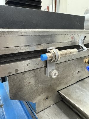
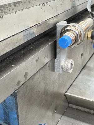
OMG. A 3D printed limit switch holder.Made the X axis proximity switch mount tonight.
The trigger will ride in the groove in the front of the table.
Still have to design that.
View attachment 60201View attachment 60202

