I've been toying with the idea of building another CNC machine. Namely a CNC mill.
I have my CNC router which is amazing for wood and even aluminum in a pinch though the high speed spindle is bit of a challenge. And steel is pretty much a non-starter.
My Weiss VM32 mill, same as a CX601/PM30 is a conversion candidate but I wanted to retain some semblance of 'manual' control to do simple operations like facing or side milling without having to do CAD/CAM.
Spent two hours with a local member of Canadian Hobby Metal Workers (the CDN version of HM) last Sunday talking CNC, steppers, servos, control software etc.
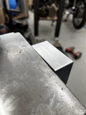
Had a lightbulb moment when John set up a facemill and quickly surfaced a block of aluminum using simple commands into the MDI interface on LinuxCNC.
That was was the part that I was missing; how to do a simple job like that without being able to turn handwheels.
Called Dave at ArizonaCNC as he makes a kit for my mill. Doublenut ball screws and all the motor mounts for three axes. Not cheap at over $1000 USD/$1400CAD. And I'd still need stepper/servos, power supplies etc. But nothing ventured, nothing gained right?
Figured I'd give LinuxCNC another shot since I have a spare PC.
While searching for servo motor spindle motor conversions I ran across a post on Canadian Hobby Metal Workers for the following:
-Masso G3 controller and pendant
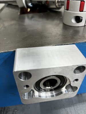
-3 axis Arizona CNC kits CX601 conversion kit, machined for:
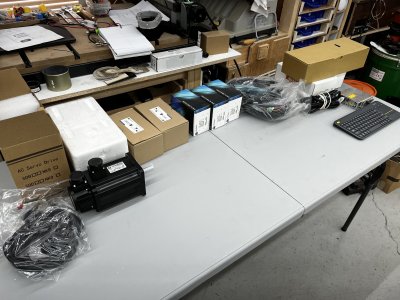
-DMM servo motors x,y,z axis(z axis has brake). Includes the cabling for motors/encoders/setup usb cables
-DMM AC servo drivers x,y,z axis
-Meanwell power supplies, filter, capacitors, breaker
-Spare R8 spindle with belt drive pulley
-some other parts, oiler, fasteners, air cylinder for toolchanger, (see pics)
-Toolchanger and belt drive was never completed, so all of this was never used or installed.
I immediately contacted the poster, and we struck a deal. $1400 CDN plus $94 shipping.
Let the electronic assembly begin!

Last edited:


