• Scam Alert. Members are reminded to NOT send money to buy anything. Don't buy things remote and have it shipped - go get it yourself, pay in person, and take your equipment with you. Scammers have burned people on this forum. Urgency, secrecy, excuses, selling for friend, newish members, FUD, are RED FLAGS. A video conference call is not adequate assurance. Face to face interactions are required. Please report suspicions to the forum admins. Stay Safe - anyone can get scammed.

Variable speed press drill

I'm glad you are curious. I do many many things out of curiosity alone. Even to the point of spending money I'll never see again.

Your explanation makes GREAT sense in all but one way. The readouts on the two units did not read zero. They typically read higher than actual.

There are two ways that rpm can be derived. One is to count pulses for a given amount of time and the other is to count time between pulses. It is as though they didn't stop counting the time between pulses.

In this latter scenario, your guess makes even more sense than in the other.

As you cause me to think about it more. This business of error detection creeps in too. As I recall, the chinglish in the description strictly talked about engine rpm. Nobody using them in an engine would ever see rpm below 150 or so. Huge engines do go much slower, but those characters would never use a $20 tach.

So ya, perhaps the signal error detection kicks in and resets or something and allows a higher count.

I'm gunna see if I can find out what I bought and get another one to take apart and play with. I think I'll get a 110V one too. It's way cheaper than flying south to go golfing.....

Edit - HEY. I just thought of something else. They were 12V units (which implies automotive). Clearly 110V units are not automotive!
I got my 110v tach today and rigged up a little test setup on my drill press. It worked fairly well and matched my handheld optical tach. Only could go down 120rpm with my pulley/drive.

I also dug out my DC one that I never permanently installed and it barely worked at all. Not sure what the issue is because I remember it working sort of okay before? I had sacrificed a very old cellphone brick as the power supply.
 
RPM comments:
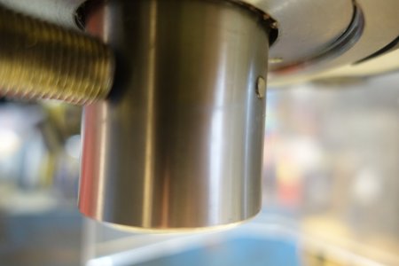
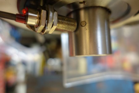
- Magnet location: I ordered my mill DRO (Ditron D80) with the RPM option. I first installed the RPM sensor (as per the instruction) by simply putting a magnet on the spindle and attaching the sensor so that there was a 3 to 6mm gap between the sensor and the rotating magnet. The unit came with several magnets - I should have guessed there was a reason for them including several magnets. The first magnet lasted a few weeks before doing a dance / jammed and broke. I installed the replacement magnet in a 3mm deep drill hole. It's now recessed and is flush with the spindle OD (see picture). This is similar to the approach that @YotaBota used when he glued the magnet onto a milled flat spot (post 98 above). Previously, while turning the spindle by hand, it was easy to move the magnet a bit and then no more RPM readings. Imagine that!
- Low-speed RPM accuracy: My mill is a benchtop 6-speed gearhead (High & Low x 3 gears). The RPM sensor readings for speeds L2 to H3 are all 0.3 to 0.4% higher than the machine-rated RPM (the machine is rated at 210 to 1,970 RPM for those gear settings). That seems to be surprisingly accurate. It's a much different story for the lowest speed (L1). It is rated at 90 RPM by the manufacturer while the RPM sensor consistently indicates that it's running at 121 RPM. Curiosity struck (apparently that's a common problem here), so I attached a marker to the spindle and counted 100 revolutions while timing it with a stopwatch. I repeated this for 120 and then 160 revolutions. The RPM calculated to be 120, 121 and 121 respectively. WOW - bang on Mr. Sensor. (BTW - that's about as fast and as far as I can count). [[Just for giggles - I put the gears in a false neutral (a spot between gears 3 & 1 where it's easy to turn by hand). I grabbed hold of the spindle and started to rock left to right in a smooth slow rhythm. I counted and swayed back and forth 50 times for one minute. I watched the screen and it varied from 50 to 54 RPM.]]

3-Phase motor with VFD:
- Over the last 6 months the Forum has taught me quite a bit about VFDs. Thanks to all - much appreciated! That's why I got the RPM option when ordering the DRO for my mill. Why do you need an RPM sensor with a gearhead? Well, I intend to (one day ?$?$) upgrade the motor (2Hp, 220V, single phase) to a 3-phase with a VFD. Thanks @YotaBota and @Marc Moreau for the eMotors and Motortek contacts, I'll look into them when the time comes. I had thought I'd get a used motor and then source a VFD but with my limited knowledge/experience that might be a bit risky. I know the Forum would be helpful with that, but one supplier for the motor/VFD makes sense.
 

Attachments

  • DSC01220.JPG
    DSC01220.JPG
    169.9 KB · Views: 7
  • DSC01218.JPG
    DSC01218.JPG
    178.1 KB · Views: 7
I had thought I'd get a used motor and then source a VFD but with my limited knowledge/experience that might be a bit risky. I know the Forum would be helpful with that, but one supplier for the motor/VFD makes sense.

If you call EMotors instead of ordering on-line, you can ask for a 1-yr volume purchase discount. I think it's only 5% but that is still $5 per Hundred.

Also, you can ask them about returned motors or open boxes. That's how I got my 2hp vfd rated motor.

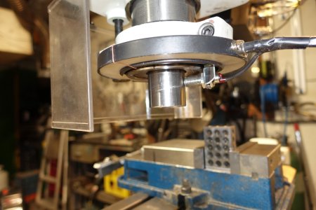
Your photos look like a lathe spindle not a mill. What are we looking at there?

While I have not done it yet, my plan is to make a double sleeve magnet holder for the tach sensors on my lathe. Essentially two abs collars turned on the lathe for a perfect fit one on top of the other. The inner collar will be drilled for the magnets using my spin Indexer to get the spacing right, and then I will slip a 2nd very thin collar over top of the first collar to retain the magnets. My hope is to avoid drilling my spindle. If need be, I will drill and tap the inner collar for a set screw, but I think a friction fit with a few dabs of blue loctite should work.
 
I must admit I took the easy way out since I wanted to keep the South Bend stock.

One of the high force magnets from Lee Valley Tools. Nestled into the screw clamp hole with a bit of hot melt I believe. The sensor is a Hall Sensor in the package similar to a TO-92 transistor clamped in a small fabricated holder.

One other point about hall sensors. They are polarity sensitive. They might work with one pole but work much better with the other pole.

SensorPlusMagnet.jpg
 
I'm in no hurry to pull the trigger on a motor upgrade & VFD - Thanks for the additional info about eMotors. I'll certainly get some more advice from you before seriously heading down that road.

Yes, it's on a mill - here's a better pic of the sensor on the spindle. FYI: just above the sensor is a circular LED light.

Securing the magnet is an important step that wasn't mentioned in the instructions. The magnet I used is tiny, 4mm diameter and about 2mm thick - so the drill hole is not significant. The first magnet I used (the one that jammed & broke) was twice as big and worked with a bigger sensor gap (about 8mm gap). I now have a 3mm gap with the small magnet but it is working perfectly. I considered using a wrap of electrical tape to hold the magnet but I wanted something more permanent (I think Mickey Mouse used tape for the magnet on his mill).

CW
 

Attachments

  • DSC01238.JPG
    DSC01238.JPG
    258.5 KB · Views: 7
I considered using a wrap of electrical tape to hold the magnet but I wanted something more permanent (I think Mickey Mouse used tape for the magnet on his mill).

CW
I've used the fibreglass tape around 3D printed hubs that have a hole for the magnet. Especially for the one on the butterfly pneumatic wrench. Glue wasn't enough. At 10,000 RPM I did lose one. One day I may find it attached to something.
 
As @jcdammeyer said - the sensor/magnet orientation is polar sensitive. If the magnet is upside down there is zero reading. It's a trial & error thing. ---Well at least on my unit.
 
I must admit I took the easy way out since I wanted to keep the South Bend stock.

That's exactly why I want to use external sleeves slipped over the rear of the spindle. I want to keep the spindle stock.

This is also an issue with mounting the display. I have not figured that one out yet. Part of me wants to put it on the wall behind the lathe and the other part wants to make a wooden saddle that sits on top of the gear box. The big lazy side of me wants to drill and tap the gearbox cover.

My lathe does not go 6000 rpm nor do I need that so I'm not too worried about using ABS pipe for the sleeves. But I suppose I could also use Aluminium.

FWIW to anyone else reading this, the real reason for using double sleeves is the difficulty of drilling inside holes. External is easy. So I decided to use a thin second sleeve on top of an externally drilled sleeve to retain the magnets. Epoxy might have been totally adequate but I don't want to be looking for a magnet stuck to the wall of my barn someplace.

Another option might have been an odd number of magnets with through holes on one side and a partial on the other. I might do this yet.

Yes, as far as I know, all Hall effect sensors are sensitive to the polarity of the magnet.

In case its not obvious, I'm looking for feedback on my ideas. I'm ALWAYS open to other ideas better than mine. I prefer such input BEFORE I start making chips!
 
My lathe does not go 6000 rpm nor do I need that so I'm not too worried about using ABS pipe for the sleeves. But I suppose I could also use Aluminium.

FWIW to anyone else reading this, the real reason for using double sleeves is the difficulty of drilling inside holes. External is easy. So I decided to use a thin second sleeve on top of an externally drilled sleeve to retain the magnets. Epoxy might have been totally adequate but I don't want to be looking for a magnet stuck to the wall of my barn someplace.
Thats how I put the magnet on my Emco spindle. The ABS has been holding up for 2 years now, i think. Its been over 3000rpm, maybe 3200.
 
Double sleeve or odd number of sensors or just glued in?
 

When I joined up, I missed the first part of that thread Darren. Thanks for the link. I've added a full read to my ToDo soon list. I love the way you think so I just know I'll learn something really useful.

I'll just have to skip over @Mcgyver 's torque vs hp comments...... LOL! I think we are finally on the same page though...... If not, we are close enough now that I can just take the odd shot like this one and laugh about it!

Your very first photo looks VERY similar to mine complete with the tool rack on the splash shield and all the forbidden tools on the headstock. Someday, I'll add a deep saddle for the headstock with dedicated spots for the things I keep there and a deep bowl for odds N sodds.

I don't have the smaller rack for drill chucks and centers though. I have just added that idea to my list of projects. I'd also like something for all the Allen's and wrenches too. Right now, mine are all in the chip tray.

Don't you find that your DRO screen gets splattered with cutting fluids?

Your spindle rpm sensor setup is more or less identical to what I am contemplating. How did you mount the hall sensor?
 
I just ran a low speed test and was able to bring the reading down to 10rpm and stay stable. There were no misses or any jumping around of the display over a 5 minute period. I also checked against the second hand on my watch and it's close enough that I couldn't see any error. That doesn't mean a scope wouldn't prove otherwise but this isn't rocket science and I don't have any degrees so I'm happy.
And for the torque groupies I tried stopping the spindle by hand at that speed and there was no give, just the sound of a bit more load on the motor/drivetrain.
 
If you want accurate rom for your machine you need a rotary counter. These units count upto 8000 counts per rev. So you can clear see what the rom is and changes as they occur from 0 to whatever.

They have issues though, the primary one is they do not like spindle loads or over speeding as it destroys them and they are expensive (I've destroyed 2 already).


I'm redesigning my system to eliminate load and speed issues as these allow the best control and measurement.
Those are cheap. Go back a decade or so an encoders ran $800 and now they are even more.

Here's a photo of a used one I have. At some point I wanted to put it on the lathe. I also have one of the $40 OMRONs you mentioned which back then weren't available at all at that price.

BEI_Encoder.jpg
 
Those are cheap. Go back a decade or so an encoders ran $800 and now they are even more.

Here's a photo of a used one I have. At some point I wanted to put it on the lathe. I also have one of the $40 OMRONs you mentioned which back then weren't available at all at that price.

View attachment 30311
The difference is definitely on the rated load 35lbs vs almost nothing. At these cheap ones from China fail at less than a pound or 2. The Omirons from an NA supplier run about $300-400 vs E-bay from Chine at $45 plus shipping, but truth be told those BEI units look a lot better but OMG $1,350.00. Have to do some searching.
 
If you want accurate rom for your machine you need a rotary counter. These units count upto 8000 counts per rev. So you can clear see what the rom is and changes as they occur from 0 to whatever.

They have issues though, the primary one is they do not like spindle loads or over speeding as it destroys them and they are expensive (I've destroyed 2 already).


I'm redesigning my system to eliminate load and speed issues as these allow the best control and measurement.
On the photo you see a freeze number probably the vibration but when I took the photo the rpm was good.. But when I fix that tach it wasn't work good I don't know what was the problem ? I try both side of the magnet and after a couple try seem to be good. I would like more infos about your omron ? how it's mount ? Thank You
 
Back
Top