• Scam Alert. Members are reminded to NOT send money to buy anything. Don't buy things remote and have it shipped - go get it yourself, pay in person, and take your equipment with you. Scammers have burned people on this forum. Urgency, secrecy, excuses, selling for friend, newish members, FUD, are RED FLAGS. A video conference call is not adequate assurance. Face to face interactions are required. Please report suspicions to the forum admins. Stay Safe - anyone can get scammed.

Turning the thread on a chuck mounting plate

I think I followed that @PeterT.

Is it possible that @SparWeb's original unfinished backplate was never intended to cut threads any longer than they are now but rather that the original intent was to bore the register ID from the other side next, but they could not figure out how to locate it properly so they abandoned the project?

Edit - I find it a bit hard to believe that anyone would make a threading tool that wasn't long enough to finish the job. So I think it was intentionally short for tool rigidity.
 
Last edited:
To put closure to the 29.5 degree issue, I checked out the matter on my lathe this morning.

My instincts were correct. It is indeed a non issue. As long as you use the compound and cross slide to position the threading tool tip precisely in the root of the last threading cut WITH ALL BACKLASH REMOVED, you can simply turn out the compound on its 29.5 degree path until it clears the face.

You will end up with a small gap between the tool and the thread face but you can just ignore it. The small gap will disappear on subsequent passes as the compound advances the tool into the thread.

This is true whether you are extending the length of an existing thread or picking up an incomplete thread that was not finished.

Note - these comments are only to address the 29.5 VS 30 degree issue, not to clarify how the compound and Cross-Slide are used together to cut threads. This latter aspect is a standard threading process that everyone follows when they cut threads and it does not affect the discussion above.

Sorry to have led everyone down the proverbial rabbit hole needlessly.
 
Late to this conversation, here is how I fixed a backing plate on a chuck when I had my 9” Utilathe with the threaded spindle nose.

@SparWeb, the main problem seems to be one of work holding.

I had the same issue with a 4J baking plate whose register bore was oversize (yes, I got carried away with the last cut machining it - the threads I got to size in the first go). My fix was as @PeterT suggested above: machine a ring (for a press fit in my case) and rebore. Here is how I held it in my lathe (figure A).

I took some round bar that fit inside the 3J chuck. I then clamped the 4J in reverse onto this bar. I used the 4J‘s centring ability to take out any runout of the BP register bore. Over bored it so that I can then press in the ring (made previously). Pressed in the ring (& some locktite for good measure), set everything up again and carefully bored out the register to size this time. I took off the 3J/4J combo to try it on the spindle by flipping it around to try it. It was a bit awkward and heavy, but it worked.

Yes the long stick-out was a concern, but the set-up was surprisingly rigid and worked very well with light cuts.

77E32C3C-7B41-4D6C-9A76-2F071808F132.jpeg


Since you don’t have the BP mounted to the 4J yet and can’t safely grip it in the 3J (and don’t have a face plate) the above method won’t work. What you could do is this (if you don’t mind having extra holes in the 4J BP - these holes could be filled with plugs after):
Remove the 3J from it’s BP. Mount the 4J BP to the 3J BP as shown in figure B. Use bolts that allow you to “bump” the 4J BP around a bit. Screw the 3J BP onto the spindle. Indicate the 4J BP bore for zero run out. Tighten the two together. Machine the threads / register bore as required. Remove assembly from spindle as often as required for fit testing by flipping it around. Do a “sanity check” for runout after each dismount / mounting cycle.
 
@PeterT it is more a matter that the bores are oversize, although oversize on @YYCHM s Standard Modern may not even screw on my South Bend. Likewise a nice fit on my SB will be loose on his SM.
I like @RobinHood - @PeterT s fix. It might do the trick for my collet chuck.
 
Last edited:
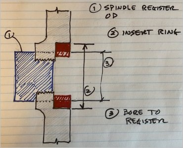
Yes, @RobinHood idea is better. Much-o simpler. I forgot the threads go straight through so plate can be screwed to spindle backwards. Then pre-bonded insert ring with extra ID stock can be machined in-situ to spindle registry OD something like so?
 

Attachments

  • SNAG-2021-12-12 12.24.15 PM.jpg
    SNAG-2021-12-12 12.24.15 PM.jpg
    73 KB · Views: 7
Yes, @RobinHood idea is better. Much-o simpler. I forgot the threads go straight through so plate can be screwed to spindle backwards. Then pre-bonded insert ring with extra ID stock can be machined in-situ to spindle registry OD something like so?

Oh oh! I am gunna go to bed and start today over. Bad omens out there.... @PeterT posted a hand drawn drawing...... :eek:o_O:eek:
 
Hi Peter,
You're right to ask - I just assumed that the thread is 2.25"-8 but that's mostly from a rough caliper measurement and I sponge a lot of info from the Grizzly 12x37 owner's manual. That could lead to all kinds of problems because my lathe is ACTUALLY a Central Machinery/Enco 12x36 built in 1986. There are many similarities but lots of subtle differences. Since South Bend was setting the standard at the time, I will take your measurement tables and see how close this lathe comes to them.

As for the chuck-to-chuck setup, I love it! Impressed by the ingenuity. I don't have any 2" round bar stock to do this with, but maybe a 2" schedule 40 pipe would do. Given a skim cut to make it circular and cut to just a length needed, that might do.

I believe that set-up would need the 4 bolt-holes in the 4-jaw chuck to be drilled, but before the center register is turned. Any risks of poor alignment by doing that?
 
Don't drill the holes until you have the chuck registering!!!! Are you sure the original threads are the correct TPI? I find it odd that it will turn on one full turn before binding up????
 
Don't drill the holes until you have the chuck registering!!!! Are you sure the original threads are the correct TPI? I find it odd that it will turn on one full turn before binding up????

Ya, this has bothered me from the very beginning too. The threads look like about 7 or 8 turns. Why does it bind up after just 1? Wrong thread pitch or wrong thread diameter or register too tight or another interference of some kind?

I assume @SparWeb doesn't have a thread gauge big enough to measure 8tpi because he said he did a rough measurent with a caliper. A caliper is plenty accurate enough at 8tpi because the pitch is over a tenth between threads. But it's hard to get a caliper inside a threaded hole.

A 1" course thread bolt is 8tpi. It will be too small for the hole, but if it will lay in the grooves, it would make an adequate thread gauge.

Or two pieces of thick paper with threading point templates on them slid against each other till they fit into two adjacent grooves, then removed and measured with a caliper.
 
Last edited:
The 1.5x8tpi backplate I got at Grizzly did not screw on all the way. I think it was more that 1 or 2 threads though. I don’t know if it was purposely undersized or just a bad job. IIRC that was the second time that I had to pick up an existing thread.
 
@Tom O - Great idea!

I have this ancient dinosaur lathe - an F. E. Reed that I got 40 or so years ago. It was my first lathe. It was probably built in 1880's. When I bought the 14x40, the Reed got relegated to polishing jobs. I keep the ways covered, but it seemed safer than using my new lathe for such gritty work.

All this is just to say that the old Reed has a 1.5-8 threaded spindle with a 1.5 OD Register at its base. I never would have guessed that.......
 
Last edited:
Or get some machinist's blue dye and let that be witness where the threads make contact. It's something I should be getting anyway.
Sorry, very busy time in my life right now - not getting out the shop to putter around as much as I'd like to.
 
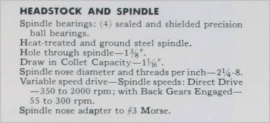
Apparently some models Logan lathes sported 2.25x8TPI spindles. ref pg-7 of this (nominal) 14" swing model. I think also other USA models back in the day.

Logan repository.

I was trying to determine the thread class or if any spindles might be have used something other than V thread form for their own purposes, but I have yet to encounter much for a defining description appearing after the ODxTPI. I cant think of a good reason why they might choose something like a trapezoidal or otherwise flat crest profile. Maybe perceived to be less bugger-up-able that sharp vees? Some trapezoidal are precision class, usually for leadscrews & such. But that translates into tight pitch diameter tolerance AND major/minor diameter clearance tolerance which V-forms don't typically adopt. A precision class spindle thread doesn't make sense to my simple brain because a registration surface is easier to manufacture & swarf debris does not play nice with tight clearance tolerances.

I know it was popular for the early Asian manufacturers to 'mostly' copy USA lathes, but they certainly had their largely undocumented deviations on multiple fronts. My King is a mixed bag or metric/imperial & the parts manual often does not fully define parts like bearings, gears etc. Just part 'number'. It could also be a case that those cheapo offshore CI backplates attempted to make a spec thread but just didn't do a great job. ie. even if the spindle is perfect, it might be getting hung up for that reason alone. Ah, the joys....
 

Attachments

  • SNAG-2021-12-13 6.19.59 PM.webp
    SNAG-2021-12-13 6.19.59 PM.webp
    19.8 KB · Views: 5
Back
Top