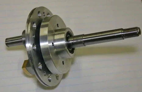
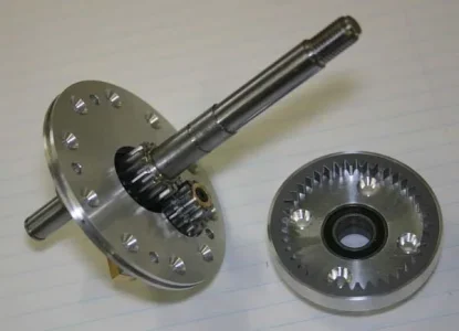
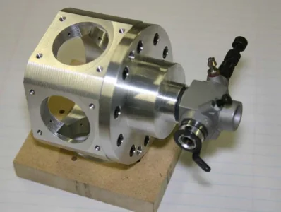
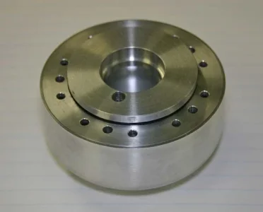
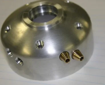
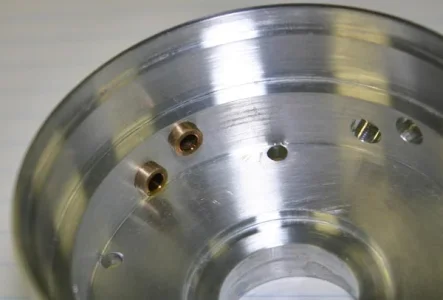
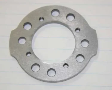
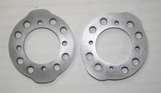
Finally! The cam plates are done. Made from A2 tool steel. Never worked with this stuff before. Its quite tough but light cuts & patience finished up OK. These need to be hardened so I've made contact with a local knife maker guy who has the appropriate equipment. Because the thinness & non-symmetrical shape & array of holes etc. I decided to try A (air) over O (oil) quenching tool steel. I figure with the work that went into them I just didn't want to add extra risk of 'potato chip' distortion if it were to hit a liquid quenched. So after heating in a stainless bag they get 'air' quenched but sandwiched between 2 aluminum plates. Then tempering to whatever temp to target hardness.
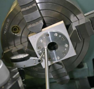
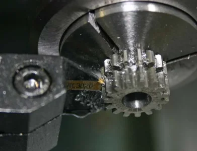
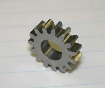
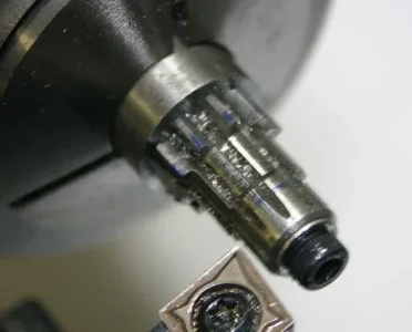
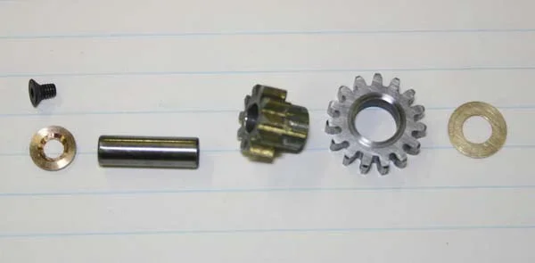
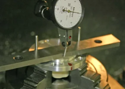
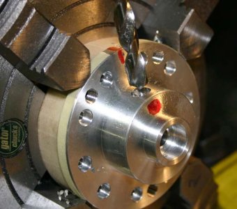
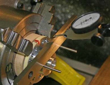
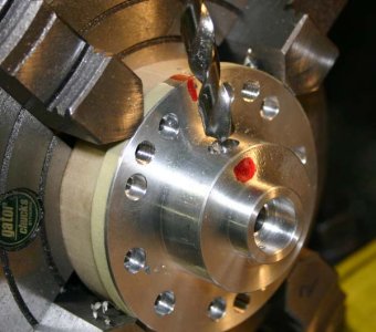
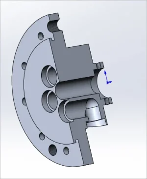
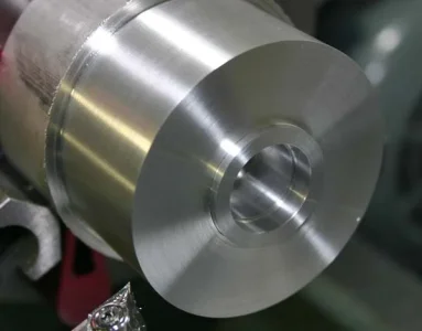
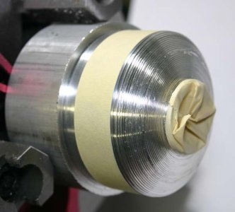
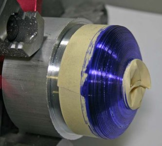
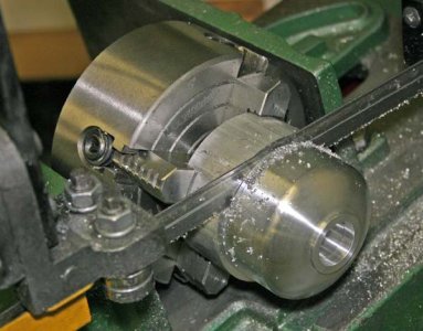
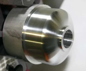
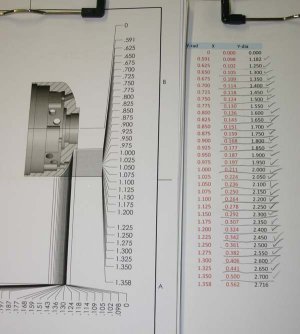
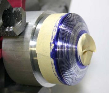
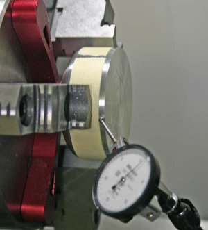
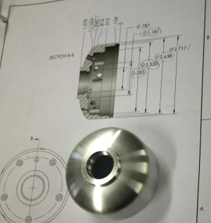
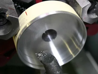
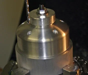
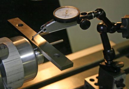
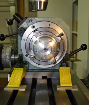
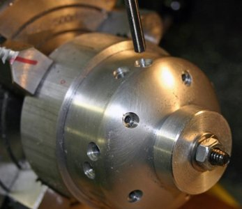
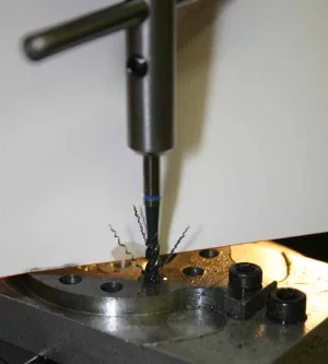
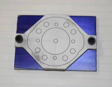
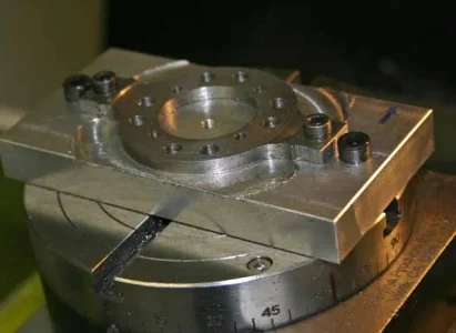
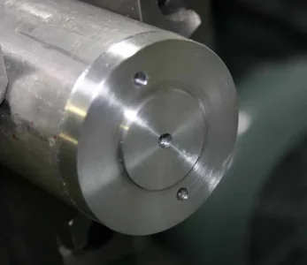
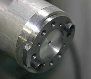
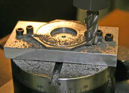
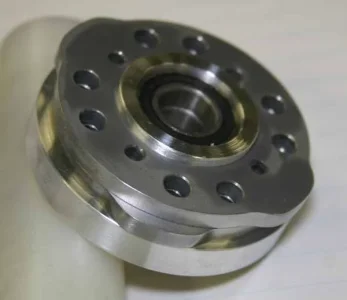
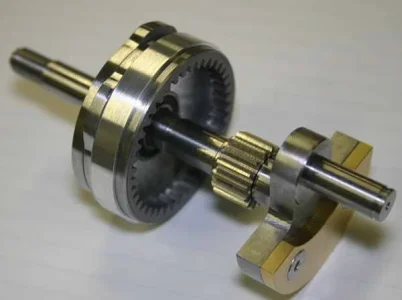
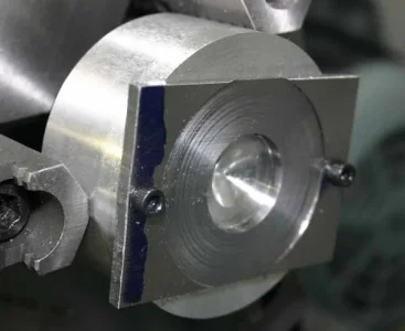
One lathe fixture was to hold the blank for center hole boring & reducing thickness to 3.5mm (metric plans) from IMP stock. Then part transferred to another mini rotary table fixture to mill the 2 (valve closed) radius arcs, then screw holes & lightening holes. One cam is intake, the other is exhaust, so the relative phasing once stacked comes about by orientation of M3 tap & clearance holes. So lots of RT angle positions to remember. Then I cut the ears off & utilized the holes to secure it to another lathe fixture for the OD (valve open) turning. Then some careful Dremel grinding to make a nice transition up the ramp of the lobe & polishing with rubberized abrasive.
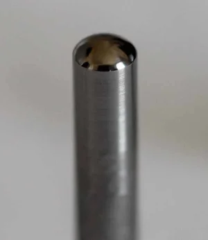
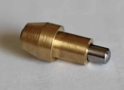
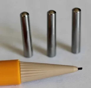
I think I'm going to make these next so I can send them out together. Basically I want the followers to be a couple Rockwell points under the cam plates so the wear is on the easier to replace part. They are made from 4mm O1 round stock. They have a hemi-ball shape on the end that runs along these cam profiles. The other end is an internal (ball mill divot) here the rocker pushrods locates into.
Attachments
-
 IMG_6941_edited-1.webp19.7 KB · Views: 16
 -
 IMG_6948_edited-1.webp16.9 KB · Views: 15
 -
 IMG_6958_edited-1.webp25.4 KB · Views: 15
 -
 IMG_6960_edited-1.webp14.6 KB · Views: 14
 -
 IMG_6962_edited-1.webp20.1 KB · Views: 14
 -
 IMG_6963_edited-1.webp15.7 KB · Views: 14
 -
 IMG_6965_edited-1.jpg32.1 KB · Views: 14
 -
 IMG_6970_edited-1.webp14.9 KB · Views: 14
 -
 IMG_6971_edited-1.webp15.6 KB · Views: 19
 -
 IMG_6972_edited-1.webp17.1 KB · Views: 19
 -
 IMG_6947_edited-1.webp23.2 KB · Views: 19

