• Scam Alert. Members are reminded to NOT send money to buy anything. Don't buy things remote and have it shipped - go get it yourself, pay in person, and take your equipment with you. Scammers have burned people on this forum. Urgency, secrecy, excuses, selling for friend, newish members, FUD, are RED FLAGS. A video conference call is not adequate assurance. Face to face interactions are required. Please report suspicions to the forum admins. Stay Safe - anyone can get scammed.

Tips/Techniques New VFD questions

Tips/Techniques
My VFD is wired with 12/2 from the panel, generally your VFD will have significantly lower start up amp draw (ie likely max is just over the running currently of motor), which another great benefit of VFD's.

One of the reasons you are starting to see compressors going to VFD.

Power in, Power out simple, control wiring occasionally requires a little more depending on the controller and VFD.
 
Just as sidebar FYI, Phil.V just posted an interesting video. I'm pretty VFD illiterate at best, but he showed some of the other aspects & considerations of retrofitting smaller offshore lathes that I would not have considered beforehand. And also some discussion regarding (in his case) the stock motor/control package as being somewhat unique or proprietary or lets say hard to source outside of the distributer vendor.

 
Here's the pic of my "frankinwire" test setup. You can see the motor was running on 18g test leads, I didn't let it run long like this but the leads didn't become fuses so there wasn't a lot of current there.

1703785952020.jpeg
 
FWIW,

I have a couple of 1.5HP motors running with VFDs, one of them for about 10 years now.

I used #14 for both the breaker to VFD and VFD to motor. 15A breaker.

1.5HP = 1120W, if the motor and VFD were 100% efficient (their not), input current required @ 240V would only be 1120/240 = 4.7A, In practice there are losses and the inductive nature of the motor results in the current lagging the voltage such that the power factor P.F. is far from (the ideal 1.0) resulting in higher imaginary or reactive current. Imaginary current is an odd thing to visualize if your not savvy with electrical details but in simplified terms for this situation it is current that flows back and forth without actually contributing to the motors output, all it does is heat the wire, hence the VFD manufactures specifying wire a gauge or two higher than what would be required for say a heater of the same power.

Fairly common for people to "over-size" their VFD for example use a 2HP VFD with a 1.5HP motor, the 2HP VFD will still draw the same current as the 1.5HP VFD BUT technically a CSA inspector could look at the VFD rating and require suitable gauge for the 2HP motor because the VFD could happily deliver 2HP all day long and what is stopping someone from later upgrading the motor making the previously approved supply wiring possibly inadequate?
 
Last edited:
The lathe currently has a 220volt 1.5 hp single phase motor. The 3 phase is a 2 hp 220v

Ah, I missed that. I guess I knew that from back during your motor search but I always forget who has what. Ya, go with 12 Gauge.

A few tips on wiring. Keep in mind I have not done my lathe yet. I'm still in the planning stage. I tend to do a lot of planning.... LOL!

The VFD can replace all of the regular control system. You can start fresh if you want. I'm not planning to do that because I'd like to retain the ability to go back to stock, but the point is that you could if you want to.

My TECO VFD has a lot of built in lathe functionality:

It has a jog function. - I'll just add a connector to the existing wiring that switches it from the contactor to the VFD jog function.

The Frwd/Rev wiring and handle on mine can be wired right into the VFD with a connector same as the jog function.

I am planning to use the VFD braking resistor functionality.

My e-stop will need rewiring to go into the VFD. I plan to add 3 parallel E - stops. Any one will kill the motor via the VFD function. I want to use the existing e-stop power switch, but that may not be possible. You don't want to kill power to the VFD when you hit e-stop. You just want to initiate braking. So I may have to replace the switch to get what I need.

I'm still working on how to do the control wiring. My TECO is not setup for a remote control panel. So this is TBD.
 
I typically size shop wiring for 20amps and 20amp breakers where or not the machines require it. What it does is reduce the stress on you breakers during start up.

The current spike during start up is caused by slippage until motor catches up to full speed at which point its at running current.

With a VFD this is almost eliminated because the VFD if adjusted correctly stays just ahead of the motor as if it was running full speed (or at least the motor thinks it is running full speed) hence the current doesn't really spike and extremely close to running currents through the entire start, stop run cycle.

This is the simple explanation.
 
A good practice, and allowed by the CEC is to use 20A circuits and receptacles for shop wiring…… along with #12 conductors.

That being said, the CEC is almost always engineering wayyy on the safe side already, so there’s no sense really going above and beyond it in my opinion.

For CEC motor wiring, conductors are sized for 1.25x full load amperage of the motor, which is more then enough.

For VFD’s, that’s 1.25x the maximum input amperage rating.

Motors also need dedicated overload protection, which VFD’s provide.

So basically FLA x 1.25 = conductor sizing amperage.

If you hire an electrician that’s what they are going to do.
 
If you’re worried about electrical noise, an alternate would be to twist the wires into a spiral and the noise between wires will be more likely to cancel out. You’d need to put the wires into a conduit of course.

I used to specify a shielded cable that was specifically for VFD’s, but that was in the early days of VFD’s, a good quality VFD is unlikely to create a problem. If it was me I’d use regular cable unless I started having weird electrical things happening while the drive is operating (like static on the TV or radio, low internet speed all of a sudden (but this one could be fixed by physically separating data and power by a foot or more))
 
Wow there is a lot in this thread already. I am a lot more confident with this stuff than say shooting or forging, so take everything I in context

A standard setup for something like this would be

2- pole 15 A breaker (do not use ground fault or arc fault)
|
14-2 solid wire
|
VFD
|
stranded 14-4 or 16-4 shielded
|
motor

Working backwards, the motor should be delta wired (l1, l2 l3) with a ground. The choice of stranded cable here is mostly for flexibility since the machine will at least vibrate, probably shift by small amounts and on many machines the motor is attached to something that actively moves like a headstock. Shielding here has a dual purpose - avoid the penetration of oil / chips / etc. and to limit the EMI. Twisting the wires will have the same effect. But at these low frequencies (say less than 400Hz) its not about improving the results for the motor - its about reducing the interference to other near by equipment. The opposite is true for higher frequency low voltage connections like Ethernet - but that's another rabbet hole

The VFD itself will have internal protection. I assume it is UL / CUL / CSA or something certified? That means that the case has a sufficient thickness of conductive metal (usually steel) to dissipate the energy inside to ground in a time consistent with normal fuse / breaker cutoff action. Thus preventing a serious fire

The 14-2 wire is standard for a 15 A circuit. Remember that the size of the wire needed depends only on the AMPs that will be pulled through and has nothing to do with the voltage or the total power. The standard charts are also calculated for 'enclosed' wires. These are wires that are inaccessible for repair, and also close to flammable materials and are not thermally or electrically shielded. I suspect everyone has the experience of wiring up a light, fan, dishwasher or something where the leads from the panel are much larger wire - this is why.

The breaker should be a 2 pole 15 A standard breaker. DO NOT use an arc fault or a GFI (ground fault) breaker. So called arc fault breakers are really fast acting breakers - the inrush current of any machine trips them erroneously. Ground fault breakers are different. They have a circuit that 'balances' the current out and current in via the black and white wires. If those currents get out of balance, then the assumption is that there must be a short to ground and the breaker will trip.

This is getting too long. So while there is a lot more to say, let's say Happy new year
 
Just to clarify, @mbond - the concerns about shielding are that the carrier frequency is in the range of 4000 Hz to 16000 HZ - but it is a square wave into an inductor. This is the very model of a radiating antenna you start with when studying radio engineering. Since a square wave has all of the higher order harmonics, that is all the higher multiples of the frequency, there is a large number of choices for resonant effects to produce an amplified radiated signal. A very dirty one, at that. It is like having a very inefficient, dirty 20-500 watt transmitter in your shop.

All these effects are minimized by using as short a cable as possible, and shielding where possible. My favourite shielding is to take armored household cable, remove the conductors and put the rubberized cable inside it. I then use metal cable glands to ground it on both ends. I get great signal attenuation by doing this.

True (and expen$ive) lead in cable for VFDs is shielded by conduictor and twisted in a Litz pattern (which further reduces radiated energy). If you have a cheap 50$ induction cooker that has expired, you can see Litz pattern wire in the coil. I used to have one for demonstration purposes, I'll post a picture if there is interest.
 

All these effects are minimized by using as short a cable as possible, and shielding where possible. My favourite shielding is to take armored household cable, remove the conductors and put the rubberized cable inside it. I then use metal cable glands to ground it on both ends. I get great signal attenuation by doing this.
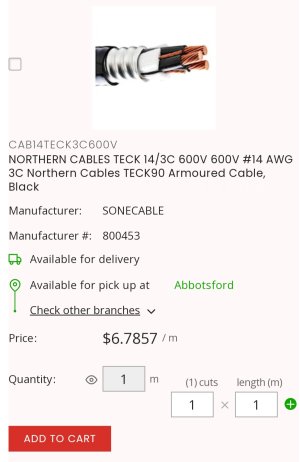
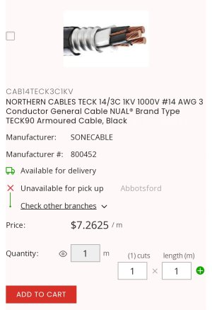
Common (in Alberta) but somewhat more spendy TECK type cable, with 1000v XLPE insulation, is readily commercially available and is almost exactly what you are describing when used with TECK rated connectors.

According to the VFD manufacturers we deal with, 1000v TECK is “approved” cable for the purpose.

This would be a readily available option for people to go and get the “proper” stuff if they so chose.

Great comment on the radio theory….
 
But where might I buy 4 conductor 14 gauge TECK cable by the foot in Alberta? I'd gladly convert my machines right away!
You likely only need 14/3 TECK. They don’t count the ground conductor in the conductor count on this cable type….. so 14/3 would be red black blue ground. 14/4 would be red black blue white ground.

Try the electrical wholesalers in your area, Eecol, Guillevin, Gescan, Wesco, Westburne…. Etc for best prices…. However, usually unless you have some sort of electrical related qualification they can be picky about selling to laymen from what I’ve heard.

If you have any industrial focused electrical contracting companies near you, they likely have a chunk of 14/4 or 14/3 in stock. If they don’t have it then I’m sure they can requisition it from above mentioned wholesalers for a small mark up.

If you are close to Taber and don’t want to search around, let me know how many feet you would like and how many connectors you would like and I can get.
 
Last edited:
I found this on the net so take it for what it's worth:

"All vfds come with instructions telling you how to size the cable and ground and its way more then 125% because of harmonics, , how the overloads class is set, ( some of our big motors are programmed to take up to 5 minutes overload at 300% before opening up so cable has to take temp overloads, freq changes, voltage, a 460v drive at 30hz its usually putting out 230v and at 90hz its 690v, motors use the cable as a heat sink, so at slow speeds the fan isn't running fast and the cable can heat up a little. This also of course is depending on how the pwm parameters have been setup.

Usually an electrical eng will have this eng'd for you. I work at a plant in Alberta and the staff electrical eng will submit this to the staff electricians or the electrical contractor. On a small drive 20hp and less since we have done a million or two we'll just look at an existing vfd in the drive cabinets."
 
@thestelster

The plants up north do have engineers that do all the thinking for their electricians. That man is obviously from one of them.

However, what he said appears to me to just be a “it’s too complicated for us (plebs) to understand at any reasonable level because of this (myriad of factors) so just copy what’s been done before by the engineers.”

This is not the case at all. There are numerous factors that contribute to cable sizing in his plant (or any plant) being above the normal allowance that the CEC gives for motor power circuits, not all to do with the VFD.

Almost all VFD installation manuals state “comply with local or national electrical installation codes and standards for cable sizing”.

Harmonics in drive applications are handled typically by reactors or filters. Not by upsizing cables.

The factors that likely are present in his plant (at least in all the large facilities in northern Alberta I’ve been involved in constructing or maintaining) are:

1) Long cable runs. From MCC to field device. Cables must be upsized appropriately.

2) Multiple cables in cable tray. Cables must be de-rated to allow for overall cable tray heating and upsized accordingly.

3) Engineer’s not wanting to screw up and go to small so just YOLO’ing the cable up a size or two because no one ever got fired for spending black gold money anyway.

4) Ambient temperature in the facility is over 30degC, cables must be upsized to account for that appropriately.

We can’t overcomplicate this for us. Yes sometimes cables are bigger then 1.25x. BUT this is not going to be relevant for us old (or not so old) dudes messing around with clapped out lathes in our garages.

Cable sizing at 1.25x is relevant for probably 90% of drive applications for other commercial purposes as well.

1.25 is adequate in almost 100% of cases for us retrofitting simple machine tools with a VFD for a motor or two.

VFD’s are the biggest rabbit hole on this site. LOL.
 
Without going too far down the rabbit hole, and skipping the math (for anyone interested, think about infinite series expansion of integratable functions into sine and cosine terms), EMI (Electro-Magnetic Interference) shielding attenuates (reduces) the interference (radiation) - important limits exist, but they are for space probes etc. It also protects the signal inside the cable from outside interference. For signals that deliver power, outside interference is a non-issue because the signal is greatly distorted by the motor etc. but outward interference is certainly a factor. For signals that deliver information, the opposite is generally true.

The shielding should be ferromagnetic - i.e. steel. And because it is subject to chips, oil etc., stainless is a good choice. What I have used is plumbing flex hose. It is meant for connecting water to a tap, toilet etc. and comes in different lengths and diameters. And you can get it cheaply at any hardware store. It is simple to adapt the fittings to an electrical box, as flexible as the stranded wire it contains, effectively contains EMI, is resistant to chips oil etc., and it has the benefit of being liquid tight. The biggest problem is threading the wires through the middle, but a cable fish makes this easy
 
Back
Top