• Scam Alert. Members are reminded to NOT send money to buy anything. Don't buy things remote and have it shipped - go get it yourself, pay in person, and take your equipment with you. Scammers have burned people on this forum. Urgency, secrecy, excuses, selling for friend, newish members, FUD, are RED FLAGS. A video conference call is not adequate assurance. Face to face interactions are required. Please report suspicions to the forum admins. Stay Safe - anyone can get scammed.

Multi-machine tachometer and machining calculator

Thoughts?

As I recall, that quill end cap is removable. You could make a new one with a built in sensor system....... The only problem is the wires that @RobinHood mentions. But maybe an external tube from top to bottom with the wires inside it would fix that.

My current thinking is a metal proximity sensor on the back gear in the head. It would sense gear teeth going by the same way that a crankshaft position sensor in a car does. But I am miles away from evaluating that. I have no desire to mess with my mill when it is working so well. So it will have wait till I have a reason to be in there anyway. In the meantime, I can use my VFD to output frequency which I can translate using a graph to RPM or by formula. It ought to be also possible to use an arduino to convert the VFD output to rpm too.
 
My concern would be the wires from the sensors getting tangled up in something. Might not be a problem when the quill is retracted, but as the quill extends further out of the housing, the wires need enough slack to follow the quill down.

I would try and mount the sensors on top of the head. Perhaps as part of a draw bar extension sleeve?

Or integrate the sensor somehow inside the head? I know, now it gets more complicated…
That all gets complicted.

I dont like complex. I plan to use a coiled self retracting stereo audio cable, It will stretch just enough to allow 6" downward travel on the quill and not be too loose when retracted. I just tested this in the shop.
 
As I recall, that quill end cap is removable. You could make a new one with a built in sensor system....... The only problem is the wires that @RobinHood mentions. But maybe an external tube from top to bottom with the wires inside it would fix that.

My current thinking is a metal proximity sensor on the back gear in the head. It would sense gear teeth going by the same way that a crankshaft position sensor in a car does. But I am miles away from evaluating that. I have no desire to mess with my mill when it is working so well. So it will have wait till I have a reason to be in there anyway. In the meantime, I can use my VFD to output frequency which I can translate using a graph to RPM or by formula. It ought to be also possible to use an arduino to convert the VFD output to rpm too.
I plan to use a future version of my machining calculator to output a 0-10v signal to control the rpm of my spindle.

The goal is simple universal.
 
Last edited:
My current thinking is a metal proximity sensor on the back gear in the head. It would sense gear teeth going by the same way that a crankshaft position sensor in a car does.

@TorontoBuilder - here is the general idea I am currently chasing for the RPM Sensor.

20230417_154157.jpg


A hole would be drilled through the casting where the probe is touching it. I know that's where the gear sits. The hole would then be tapped to take the 8mm-1.0 thread of the crankshaft sensor I'm holding. The sensor is a proximity sensor that detects the passing of the gear teeth. No magnets are required. This one is an 8mmx3mm sensor which means it must be within 3mm of the teeth to see them. It creates one pulse per passing tooth. The pulse will require shaping and filtering to make it work with a counting circuit. It will easily work to 6000 rpm on the mill with a rock solid display because of the high number of teeth on the gear. If I can find a smaller one or one that works with a bigger gap, I'll use that instead.

But installing it will require removal of the motor and gear cover assembly to prevent chips from entering the gear case. So it must wait. Which might be a very long time cuz I love that mill just as it is and don't want to mess with it right now. Too many other projects on the go. I might make some simpler system that doesn't require taking my mill apart in the meantime.

I suppose I should also rig up a circuit and test it on a gear chucked in the mill or the lathe.
 
@TorontoBuilder - here is the general idea I am currently chasing for the RPM Sensor.

View attachment 33712

A hole would be drilled through the casting where the probe is touching it. I know that's where the gear sits. The hole would then be tapped to take the 8mm-1.0 thread of the crankshaft sensor I'm holding. The sensor is a proximity sensor that detects the passing of the gear teeth. No magnets are required. This one is an 8mmx3mm sensor which means it must be within 3mm of the teeth to see them. It creates one pulse per passing tooth. The pulse will require shaping and filtering to make it work with a counting circuit. It will easily work to 6000 rpm on the mill with a rock solid display because of the high number of teeth on the gear. If I can find a smaller one or one that works with a bigger gap, I'll use that instead.

But installing it will require removal of the motor and gear cover assembly to prevent chips from entering the gear case. So it must wait. Which might be a very long time cuz I love that mill just as it is and don't want to mess with it right now. Too many other projects on the go. I might make some simpler system that doesn't require taking my mill apart in the meantime.

I suppose I should also rig up a circuit and test it on a gear chucked in the mill or the lathe.

I've never seen the inside of the head of a bridgeport, except on a video. I looked at the drawings and exploded parts lists in great detail. I just didn't want to face all that in the short term, and I am pretty happy with my solution. I've actually refined it since looking in further detail at the parts in question.

I'm now going to make a mount that secures an enclosed pcb mounted hall sensor to the lower face of the cap on the bottom of the quill. My pcb with have a stereo audio jack rather than the 3 pins shown in the image below.

25446179_bee22745-1f17-47ba-adc5-4118c7b97119_700_700

The smallest cable connector, allows for easy disconnection of the sensor cable as required.

MJ-3502.jpg


Mounting to the lower face of the cap wont prevent any movement of the quill, so is preferable.

IMG_20230417_160617789.jpg


Beingon the bottom face makes the sensor perfectly located to read magnet array on the spindle that protrudes thru the central bore. I'll mount the pcb at 90 degrees to the two holes for a pin wrench so the sensor wont interfere with disassembly in the future if required. There is really a lot of real estate there to use as well.

IMG_20230417_160610430.jpg
 
Mounting to the lower face of the cap wont prevent any movement of the quill, so is preferable.

Looks good TB. I prolly should have warned you but didn't:

There is a double screw in there where the R8 Alignment Pin is.

The end cap lock screw torque is important. It will actually distort the quill enough to make it stick.

I might look at making a new end cap with an integrated speed sensor. I like your audio jack - it makes replacing the wiring easy. Prolly best to just plan on breaking it and make a few extras. That would relieve me of the burden of waiting to get into my head.

This is one time when a very small magnet will be a very good idea.
 
I have pics of what my quill scale mount will look like. I thought I'd posted this before but don't see it now.

1681954123753.webp


I still have to mill the magnet groove... and to add two grub screws along a vertical line 1/8" to the right of the cap screws that mount the bracket so that the front plane bracket can be adjusted, to offset the effect of the casting sloping slightly downwards toward the right, as well as top to bottom adjustment if required.

IMG_20230419_204046397 (1).jpg


IMG_20230419_204056358 (1).jpg
 
somehow this thread has morphed into our Mill DRO install as much as being about the machining calculator


I may as well continue... here is one more partially machining piece of the quill DRO scale puzzle.

274681154428772594.jpg


318591334756913298.jpg
 
A little bit more done today.

I still need to mill the slot for the tape... and I needed more M3 cap head screws to mount the read head.

I did have a couple of problems related to lack of good carbide drills... I used a transfer punch to mark the holes for the mount in the quill stop nut, and I started drilling the holes but nada, zip, I could barely make a dent.

This is where I made a huge mistake. I should have stopped, purchased a good drill bit and used a corded drill with a much higher rpm to drill the nut another day.

But impatient me forged ahead with what I could find in the shop.. a 2 flute 1/8" mill with a point. I went to drill the first hole in the nut and the cutter also was slow going, until it shifted sideways and started cutting fast. So hole got drilled but not in line with the hole in the mount. I cursed and went to drill the second hole. When the cutter broke through the back of the piece the cutter snapped off in the hole... curses. It was a very expensive cutter...

So this nasty mess will have to do until I can machine an entirely new quill stop nut along with the quick push button microstop


IMG_20230421_190236197.jpg


IMG_20230421_190348012.jpg
 
Worth noting, we decided to just use a simple locating pin to align the read head mount. One side of the pin fits the bore in the quill stop nut with a friction fit. The other if a friction fit for a 1/4" diameter bore in the mount. The midsection of the mount is the same thickness of the nut, and the pic locates it perfectly in the center.
 
work on the Milling machine DRO and tachometer mount has came to a screeching halt this past Saturday with a family emergency and I've yet to be able to get to the shop to continue work on the project.

I'd have liked to get back to it today buy today I had to take the dogs into the vets for dental cleaning and some extractions.

PSA: Short snouted dogs have terrible teeth since their mouths are too small for the amount of teeth they have.. dont frequent breeders for short snouted dogs. Rescuing is okay but don't feed the demand for poor inbred dogs.
 
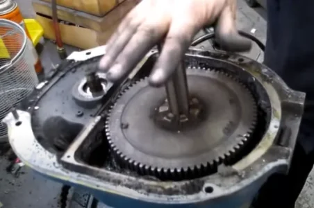
For those who haven't looked inside the head of a variable speed bridgeport... you can see below what you have to work with in terms of placing a magnet array and hall effect sensor. This is why I've leaning towards the quill mount route

1682631572662.webp
 
For those who haven't looked inside the head of a variable speed bridgeport...

You have that same mess on the pulley head too.

I had been planning to go one more level down to the back gear assembly which is geared directly to the spindle by accessing it at the spindle side (front) it is a 1:1 with the spindle.

1682631572662~3.png


Drill a hole here and underneath there is the drive gear for the spindle from the back gear. The teeth can be used with a proximity sensor.

Basically the exact same system as used in an automotive engine as a crankshaft position sensor.
 
For those who haven't looked inside the head of a variable speed bridgeport... you can see below what you have to work with in terms of placing a magnet array and hall effect sensor. This is why I've leaning towards the quill mount route

View attachment 33993

Underneath the upper drive belt, pulley and then the brake shoe assembly you find this aluminum plate protecting the bull gears... It takes a lot of disassembly to get to this point. If your head does not need any work this is a task most people likely prefer not to undertake.

1682632906380.webp


Here is the large bull gear itself

1682633518156.webp


Now @Susquatch was thinking of drilling the casing and inserting a hall sensor to read the gear teeth.

Since I'm going to be disassembling the head of our mill to rebuild it, I'm planning to investigate this option in detail despite the likelihood of rejecting it.

One immediate complication is that it appear that a sensor must be located right where the flange of the bull gear housing is located. This may be problematic because it looks like the flange is narrower than the width of the typical 12mm hall effect sensor housing that would have to pass thru the flange area. Additionally, the large bull gear changes height vertically, moving up or down to engage or disengage the small gear to the rear of the head as the speed range is changed from low to high gear.

This vertical movement may impact the sensor operation, therefore before I would select this sensor location I would want to test such a set-up to ensure reliable sensor triggering prior to undertaking any installation work.

Here is how I'd test this configuration:

First I'd measure the height of the bull gear position in both low and high speed setting in relation to a fixed reference point, and then calculate the bull gear's vertical offset in relation to the hall effect sensor for both high and low speed operation, as well as calculating the mid-point between the upper and lower heights.

Then I'd locate and mark that mid point plane on the inside of the bull gear housing, and hope it does not coincide with the top flange of the housing.

Then I'd remove the bull gear from the mill head and use it to construct a test apparatus, installing the bull gear on a mandrel held between vee blocks or similar so that the bull gear can rotate freely.

Then I'd rig a test stand to affix my sensor head to in order to position the sensor at the two offsets to the gear when the mill is running in low and high speed.

Then I'd power up the sensor and connect it to a oscilloscope to verify that the sensor triggers each time a gear tooth passes the read head. I'd reposition the test stand to calculate the maximum vertical and horizontal offsets where the sensor will trigger at the passing of each tooth. Based on this data I'd determine if the sensor head can be physically located in a position where is will work reliably in situ under both high and low speed operation.

Another potential issue is potential fouling of the sensor over time, since the grease packed in this housing gets filled with super fine metal particles which could impact the magnetic fields sufficiently to interfere with triggering the sensor reliably.
 

Attachments

  • 1682633109398.webp
    1682633109398.webp
    30.4 KB · Views: 0
You have that same mess on the pulley head too.

I had been planning to go one more level down to the back gear assembly which is geared directly to the spindle by accessing it at the spindle side (front) it is a 1:1 with the spindle.

Drill a hole here and underneath there is the drive gear for the spindle from the back gear. The teeth can be used with a proximity sensor.
I was still writing my follow up when you posted your reply... bad athritis today means slower than normal speed
 
One immediate complication is that it appear that a sensor must be located right where the flange of the bull gear housing is located. This may be problematic because it looks like the flange is narrower than the width of the typical 12mm hall effect sensor housing that would have to pass thru the flange area. Additionally, the large bull gear changes height vertically, moving up or down to engage or disengage the small gear to the rear of the head as the speed range is changed from low to high gear.

A proximity sensor is not a hall effect. No magnet is required. Just iron (steel, stainless, cast iron, etc)

I have one in hand that is 8mm. It will fit in the flange.

This vertical movement may impact the sensor operation, therefore before I would select this sensor location I would want to test such a set-up to ensure reliable sensor triggering prior to undertaking any installation work.

Are you sure that gear goes up and down? I didn't think so.

It takes a lot of disassembly to get to this point. If your head does not need any work this is a task most people likely prefer not to undertake.

Precisely why I'm not doing it until I'm in there anyway. IMHO, it's the kind of thing that should have been drilled and tapped and then plugged during manufacture. But I'd be kidding myself to hope for that. It can wait. In the meantime, I'll prolly do exactly what you are doing and make a nose extension. With some luck, and some attention to detail, I might only lose a 1/4 inch or so.


Another potential issue is potential fouling of the sensor over time, since the grease packed in this housing gets filled with super fine metal particles which could impact the magnetic fields sufficiently to interfere with triggering the sensor reliably.

No issue, these kinds of sensors screw in and out. It's easily removed for cleaning or replacement. Because they are a standard automotive part, they are high volume and cheap. The gear teeth self clean because they engage each other.
 
A proximity sensor is not a hall effect. No magnet is required. Just iron (steel, stainless, cast iron, etc)

I am not trying to mansplain but, gear tooth speed sensors are typically non-contact, solid-state, ferrous detecting, hall effect devices with a switched output.

I'm hoping the mid-point is below the flange so I wont be limited.

Are you sure that gear goes up and down? I didn't think so.
Well the wheels on the bus go up and down...

I believe that in low speed the large bull gear sits lower and engages with the small bull gear, while in high speed the large bull gear is raised and does not engage with the small bull gear. But am I sure about the bull gear while in operation, well not 100%.

But it does go up and down when using the speed selector handle, and it is mounted on 3 springs.

Precisely why I'm not doing it until I'm in there anyway. IMHO, it's the kind of thing that should have been drilled and tapped and then plugged during manufacture. But I'd be kidding myself to hope for that. It can wait. In the meantime, I'll prolly do exactly what you are doing and make a nose extension. With some luck, and some attention to detail, I might only lose a 1/4 inch or so.

Agreed, they should have made the machine to accommodate a sensor.

I've got the spindle/quill sensor mount worked out so that no height is lost.... so I will make that part anyway, and perhaps chnage on the rebuild.
 
I believe that in low speed the large bull gear sits lower and engages with the small bull gear, while in high speed the large bull gear is raised and does not engage with the small bull gear. But am I sure about the bull gear while in operation, well not 100%.

But it does go up and down when using the speed selector handle, and it is mounted on 3 springs.

@Susquatch, Brent seems to concur when you asked how the back gear works.
When you move the speed change lever from high to low, instead of driving direct from the belt, you lower a large drive gear to mesh with a smaller “back gear” and your mill will drive in reverse unless you change the direction of the motor, hence the motor switch says “High and Low” instead of forward and reverse.

The lever stop you fixed raises and lowers the large drive gear to mesh with the back gear.
 
I am not trying to mansplain but, gear tooth speed sensors are typically non-contact, solid-state, ferrous detecting, hall effect devices with a switched output.

No worries about mansplaining with me! Mansplain away TB! I look at it as an opportunity to learn something not to be proven right or wrong.

How about this instead. When I describe a "proximity sensor" I am talking about an inductive device that uses a moving ferric object to induce a field in a coil. They work well at high speeds and begin to lose signal strength at low speeds. They don't work at all when stopped. A Hall sensor senses a charge difference across a plate in the presence of a magnet. They work best at low speeds and even work just fine when not moving at all. Inductive "proximity" sensors are best used on something that either moves fast or has lots of inputs such as the ring gear on the flywheel of an engine or in our case the large gear in a mill. The difference between a hall sensor and a proximity sensor is that the hall requires a magnet and uses the hall effect to sense the presence of that magnet, and a proximity sensor does not need a magnet and uses the inductive effect to sense moving ferrous objects.

I think the confusion arises because some hall effects use a moving ferrous shield that Interrupts (shunts) a magnetic field between a fixed magnet and the hall sensor.

Well the wheels on the bus go up and down...

I believe that in low speed the large bull gear sits lower and engages with the small bull gear, while in high speed the large bull gear is raised and does not engage with the small bull gear. But am I sure about the bull gear while in operation, well not 100%.

Hmmmm...... On the pulley drive system (my Hartford) the small rear gear goes up and down not the big front gear. I confess that I'm surprised that they reversed this on the varidrive. I do know that the side controls for the engagement are different so perhaps the gear engage/disengage are different too. Here are the blow-up parts drawings. You can see how the small gear (54) on the pulley drive moves, you can even see the shift forks (56). I had planned to put the sensor on gear (50) because it's big with lots of teeth, is directly coupled to the spindle for reliable rpm output, and I didn't think it moved up and down. I can't see that on the varidrive. I had assumed (perhaps incorrectly) that the two units were the same from the split down.

Pulley Drive

Screenshot_20230428_072930_Chrome.jpg


Here is the var-drive breakdown. It's not clear here (to my eyes anyway) how either gear is moved. But I don't see that shift fork system of the pulley drive there anyplace. I also don't see splines - just a key. That raises doubt in my mind about how it works. It's unlikely that it would slide up and down on a key. More likely that some other part like a sleeve coupling moves.

Anyway, this too will be simple when solved and we will both learn something!


Screenshot_20230428_072741_Chrome.jpg
 
Back
Top