• Scam Alert. Members are reminded to NOT send money to buy anything. Don't buy things remote and have it shipped - go get it yourself, pay in person, and take your equipment with you. Scammers have burned people on this forum. Urgency, secrecy, excuses, selling for friend, newish members, FUD, are RED FLAGS. A video conference call is not adequate assurance. Face to face interactions are required. Please report suspicions to the forum admins. Stay Safe - anyone can get scammed.

Multi-machine tachometer and machining calculator

TorontoBuilder

Ultra Member
The first iteration of my friend and I's multipurpose tachometer and machining calculator is complete and passed the first round of testing.

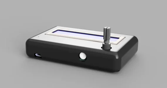
The design is based on a custom circuit board with an inexpensive LCD display and a single encoder for the data input in order to keep the costs very affordable. The board features a ESP32 MCU with has a hybrid Wi-Fi & Bluetooth chip but does not currently utilize those functions. The boards have a mix of surface and thru mount components and are assembled in Ontario. The cost to produce the board per unit is about $10 without a case, hall sensor or the magnets and magnet mount.

The board has very low power consumption, and accepts a 5.5v power supply so it can run off a laptop, a wall wart phone charger, or an external battery as shown.

The controller calculates the machine speeds and feeds for the Lathe, Mill, Drill, and will soon calculate the same for 2x48 and 72 inch belt grinders. It also functions as a revolution counter for making springs and electrical windings.


AMWts8Bp5po87Uf487a9pi7U8x-R7ikIhHVWiwt08iW1ONhTw0zVV6GOnUAB3TBGGsN9yU56yiA-CQhk0AndkWmDcMghrtqAkbGo9L4ttDREVw9M3UpGhFiYjsyCEsw1LiP5CcWsoiJG6zONxuGiUHP3eVIy=w568-h757-no


Version 2.0 will have a minor layout change to provide better cable management and ergonomics.

1677881211128.webp


Next steps are to design mounts for our Bridgeport Mills, 3 different lathes and 2 belt sanders
 

Attachments

  • 1677881155751.webp
    1677881155751.webp
    10.2 KB · Views: 2
Here is the count function in action.

The counter actually counts the pulses, and divides by the number of magnets and commences an incremental count. So in my case it counts 60 degree segments and displays 0/6, 1/6, 2/6, 3/6, 4/6, 5/6, 1_6/6 until one rotation is completed then resets the 60 degree number and displays 1 0/6. Then keeps on counting up.

Pushing the encoder wheel rests the count. Very simple way to wind magnet wire and ensure the exact same number of loops of wire, which is handy when winding many bobbins with wire.

 
Lathe mode.

One issue that I think could be tweaked is the rpm smoothing. I think the delay is too long so the display overshoots on start up and takes a couple seconds to become stable. But that is a minor issue.

 
Nice in both counts!

One issue that I think could be tweaked is the rpm smoothing. I think the delay is too long so the display overshoots on start up and takes a couple seconds to become stable.

Yes, it needs a little smoothing. No biggie. Lotsa ways to do it. I assume you already did a rolling average. It could also benefit from an update regression so it changes quickly with bigger changes and slowly with smaller changes. That would fix the display updates after the machine is stopped.

Question - I know you are pressing something to select the options. Is that built into the selector dial or are you pressing something else someplace that I can't see?
 
Nice in both counts!


Yes, it needs a little smoothing. No biggie. Lotsa ways to do it. I assume you already did a rolling average. It could also benefit from an update regression so it changes quickly with bigger changes and slowly with smaller changes. That would fix the display updates after the machine is stopped.

Question - I know you are pressing something to select the options. Is that built into the selector dial or are you pressing something else someplace that I can't see?
pressing the encoder wheel in activates the switch
 
it is a simple EC11 encoder. available everywhere for about 2 bucks.

20 steps per revolution, acts as a switch when pressed down as well

Hahaha. Amazing how simple things fly under the rader so easily sometimes!

Thank you!
 
In practical use will you pick the machining mode, material, size of cutter and it says 348 rpm ?
 
In practical use will you pick the machining mode, material, size of cutter and it says 348 rpm ?
So what the controller currently does is read the spindle rpm, from which it will calculate the surface feet per minute based on input diameter and the rpm of the selected drive system. It will calculate and display the feed rate based on the read rpm, and the input chip load. First the user selects the speed to yield the desired SFM. Then enters the chip load based on the tool and material, and obtains the recommended feed rate.

This first iteration requires you the user to rely on machining data charts such as charts for recommended SFM rates for various materials, and chip loads based on tool diameter and material types. A future version will move to look up tables in place of external charts. We did not go with that to start because we wanted to first work out how we will use the encoder and not require a lot of time to input data. It turned out we can quickly enter data and will be able to scroll through data tables very easily.

So the next steps are to revise the data entry order to first set the mode, then select material via choice of material tables, this will populate the recommended SFM rate. Then we will have it select the cutter data which will populate the chip load field, and in milling it will populate the diameter entry. Then when the spindle is running it will spit out the SFM and feed rate, resulting in a totally self contained process without any external data required. The ESP32 was used because it has the memory capacity for these tables.

This is a simple firmware update.
 
I’d love to see this. My iteration has one dial for material, one dial for cutter diameter, reads spindle RPM and displays spindle RPM, material, cutter diameter, recommended SFM, and current SFM. 20x4 LCD, single Arduino Nano board. I ran out of program memory so my lookup tables for material and cutter size can only hold twelve values, and I had to use analog pots for data entry because the Nano only has two interrupts pins and one of them is for the tachometer. With more interrupts I could have used rotary encoders for data entry. With more memory I could put in a more comprehensive materials database, and have a dial to select cutter type.
 
With more interrupts I could have used rotary encoders for data entry. With more memory I could put in a more comprehensive materials database, and have a dial to select cutter type.

There is lots of space between the nano and the mega. I believe the Canaduino Black Pill has both the memory and the Interrupts to handle your needs and at $15 is still quite affordable. It is STM32 based instead of ESP32. If you go that route, you might want to wait a while though. They are out of the breakout boards for it and are not making any more because he is close to releasing an upgraded board with more features. I have the last 2 of the old boards.

Lastly, just an idea for you. At the relatively low speeds of a milling machine or a lathe, there are lots of ways to get speed type inputs that do not require using interrupts.
 
I’d love to see this. My iteration has one dial for material, one dial for cutter diameter, reads spindle RPM and displays spindle RPM, material, cutter diameter, recommended SFM, and current SFM. 20x4 LCD, single Arduino Nano board. I ran out of program memory so my lookup tables for material and cutter size can only hold twelve values, and I had to use analog pots for data entry because the Nano only has two interrupts pins and one of them is for the tachometer. With more interrupts I could have used rotary encoders for data entry. With more memory I could put in a more comprehensive materials database, and have a dial to select cutter type.

I'll send you one when we have the second iteration up and running with the new boards. The large amount of flash memory on ESP32 is very handy.

To keep our controller intuitive and simple we limited things like what data gets displayed. When we implement the look up table I think we can rely on just displaying the recommended SFM once and then display only the current SFM. My partner insisted on cheap and simple and I think it was the way to go.
 
The first iteration of my friend and I's multipurpose tachometer and machining calculator is complete and passed the first round of testing.

The design is based on a custom circuit board with an inexpensive LCD display and a single encoder for the data input in order to keep the costs very affordable. The board features a ESP32 MCU with has a hybrid Wi-Fi & Bluetooth chip but does not currently utilize those functions. The boards have a mix of surface and thru mount components and are assembled in Ontario. The cost to produce the board per unit is about $10 without a case, hall sensor or the magnets and magnet mount.

The board has very low power consumption, and accepts a 5.5v power supply so it can run off a laptop, a wall wart phone charger, or an external battery as shown.

The controller calculates the machine speeds and feeds for the Lathe, Mill, Drill, and will soon calculate the same for 2x48 and 72 inch belt grinders. It also functions as a revolution counter for making springs and electrical windings.


AMWts8Bp5po87Uf487a9pi7U8x-R7ikIhHVWiwt08iW1ONhTw0zVV6GOnUAB3TBGGsN9yU56yiA-CQhk0AndkWmDcMghrtqAkbGo9L4ttDREVw9M3UpGhFiYjsyCEsw1LiP5CcWsoiJG6zONxuGiUHP3eVIy=w568-h757-no


Version 2.0 will have a minor layout change to provide better cable management and ergonomics.

View attachment 31540

Next steps are to design mounts for our Bridgeport Mills, 3 different lathes and 2 belt sanders
Is it going to be open source?
 
Back
Top