-
Scam Alert. Members are reminded to NOT send money to buy anything. Don't buy things remote and have it shipped - go get it yourself, pay in person, and take your equipment with you. Scammers have burned people on this forum. Urgency, secrecy, excuses, selling for friend, newish members, FUD, are RED FLAGS. A video conference call is not adequate assurance. Face to face interactions are required. Please report suspicions to the forum admins. Stay Safe - anyone can get scammed.
You are using an out of date browser. It may not display this or other websites correctly.
You should upgrade or use an alternative browser.
You should upgrade or use an alternative browser.
Locking Threaded Chucks
- Thread starter David
- Start date
Would a set screw (brass tipped of course) thru the stub onto the threads affect runout? Much easier than slitting the stub and wouldn't affect the strength of the stub.
Some people report that it works, the same people that claim threaded spindles aren't a problem in the first place LOL.
So far what I call a flange, @140mower calls a spigot and now you are calling it a stub.... What is it? A boss?
140mower
Don
Don't think it is a boss, 'cause it don't look nuthin like the fellow that said we'd be doing as many 12+ hr days as we can stand until the end of March....Some people report that it works, the same people that claim threaded spindles aren't a problem in the first place LOL.
So far what I call a flange, @140mower calls a spigot and now you are calling it a stub.... What is it? A boss?
My terminology is probably not so good, my passion for the hobby is much greater than my experience level.
Pick one LOL, as long as we all know it's the same thing all is good.
After looking it up, flange was way out to lunch LOL. I think boss is right term.
I'll be honest, I don't like this. Too easy to crack through and zingoes the front half. And then @ShawnR s moose let's loose.
ESPECIALLY if it's cast iron!
After looking at all the photos and discussion and especially the risk, I am inclined to think this needs a rethink.
For starters, it needs a steel backplate not cast iron. Second, even steel needs a relief hole to reduce stress concentrations. Third, from the photos, the clamping all seems to take place on the unthreaded section of the hub nose (my preferred terminology). I don't like that. I'd prefer a way to tighten the thread grip. Fourth, a brass nosed grub screw might be too easily stripped.
What a huge dog's breakfast....
How about a new adapter between the threaded nose and the chuck? Something that Clamps down on the threaded nose with a vise grip from both sides (front and back) and incorporates a new flange that acts like a backplate. All chucks are then machined to precision fit the new backplate sort of like a D1-X system. I'm envisioning a double collar (like a double nut) to hold the flange to the spindle nose. But I'm not sure there is enough thread there for that. Might need to think about three or four thread wedges instead.
It's a lot of work but would be MUCH safer!
It's either that or abandon reverse totally! At least that's what I'd be thinking......
That was my first reaction when I looked at one of the chucks that came with my 9” Utilathe.I don't like this. Too easy to crack through and zingoes the front half.
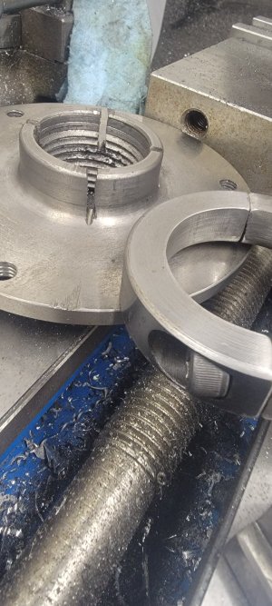
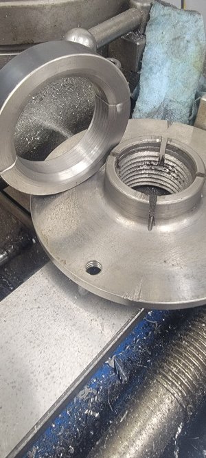
Turns out the chuck was super high quality, made in Japan. The flange bore was a very close fit to the spindle nose flat. The locking collar was made from steel - also a close fit to the flange OD. A single SHCS locked it.
I did some testing: screwed the chuck onto the spindle without bottoming it out against the rear register (about a quarter turn shy, so there was a visible gap). Tightened the locking collar. Took a foot long adjustable spanner and grabbed one of the jaws. Selected highest spindle speed. Blocked the motor by pinching it with wood. Now pulled hard on the spanner. Every time the motor belt slipped. The chuck never spun on the spindle - either forward or backwards. That was proof enough for me that this clamping system works and it is safe to run the lathe in reverse under normal operating conditions.
The close fit of the components, the elasticity of the CI and the strength of the steel collar seem to work well together in this case.
The chuck / collar were exactly like @dfloen has modified his.
@Susquatch , totally agree with the stress concentration point where the saw cuts end. One could try and drill radial holes first and then have the saw cuts end in them. Would go a long way to mitigate the potential… OTOH, the Japanese engineers did not think it was necessary…
I don't get it?And then @ShawnR s moose let's loose.
Last edited:
The one I made above is made from an old overhead door pulley.thats some tough cast iron. The collar id and the od where it sits are inversly tapered by a degree or 2 so the collar cannot slide off. That's just an off the shelf shaft collar from the bearing supply house thats bored to fit.
Search on moose......I don't get it?
Just moose. Not sure it was Shawn. But I'm still laughing.
Cast iron is surprisingly flexible over a short range. My Ox/Ac instructor asked us whether steel or cast iron was stiffer. We all thought cast iron. Then he held out a cast iron and a steel welding rod. The cast iron drooped like a wet noodle compared to the steel one.
It isn't really whether it's more flexible. It is more brittle. Brittle metal cracks.
The one I made above is made from an old overhead door pulley.thats some tough cast iron. The collar id and the od where it sits are inversly tapered by a degree or 2 so the collar cannot slide off. That's just an off the shelf shaft collar from the bearing supply house thats bored to fit.
All good. I'm just being paranoid. I'd be happier with good quality steel. And happier still with a better totally different retention system.
It wasn't you, it was @CalgaryPT . Sorry for the mix up.I don't get it?
In my defense, it sounded like your kind of humour.


