• Scam Alert. Members are reminded to NOT send money to buy anything. Don't buy things remote and have it shipped - go get it yourself, pay in person, and take your equipment with you. Scammers have burned people on this forum. Urgency, secrecy, excuses, selling for friend, newish members, FUD, are RED FLAGS. A video conference call is not adequate assurance. Face to face interactions are required. Please report suspicions to the forum admins. Stay Safe - anyone can get scammed.

Lathe Stall

Not familiar with the "direct drive-back gear" system, is there a gear change or belt change from pully pair to another pair. I ask this as i revisited your belt photo's and it appears to show common damage from the belt riding on the inside flat, and burnished sidewalls with chunks broken away from not gripping sidewalls enough for a good grip. Belts with those characteristics on farm equipment usually indicate the driven pully has been worn to a slipping condition on the sidewalls.
 
If back gear works great but direct drive slips, he culprit is most likely the pin to engage the direct drive. It is either sheared or not engaged.
 
So I set my phone camera up under the rear countershaft (the main shaft and cone pulley system that connects directly to the motor). I stalled the lathe out, when I stalled it the shaft continued to rotate while the cone pulley arrangement remained stationary. I’m no expert, but does this point to a burnt out clutch pack?
 
Take it apart, clean it and check for proper engagement. Adjust it to specs and replace any worn parts.

Some of those cone clutches had hardwood as a friction material. That can be replaced if worn out.
 
5399F585-09AA-4718-BFA6-1FFCE3F8DF4F.jpeg

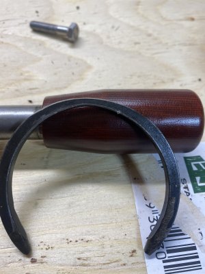
There is a picture of the cone pulley removed from the clutch hub. I assume that small 1/8” strip in the centre hub grove is the friction material?
 
I would think that is the friction material. In your second picture it looks like there is uneven wear on the ring (at least as far as the ID / OD is concerned)

Do you think that this is a “dry” clutch - meaning it should be cleaned and run without lubrication? It might help in the meantime while you source or fabricate a new friction ring.
 
What lathe is that out of Ben? You probably told us what you run, I just never paid attention, sorry.
 
It’s a Clausing 100 mk3, that ring appeared to made of steel and I assume now it’s just a retaining ring. Is it possible the clutch only consists of a hardened steel hub that cams out to engage the cone pulley?
 
What does the cone pulley look like? Post an image with it held beside the clutch assembly in it's approx installed location please.....
 
Ben, we (my son and I) have figured out what is wrong with your clutch: the expanding clutch adjusting bolt (part # DL 676 in the manual) has spun 90* in its bore. The wedged sides no longer engage on the clutch wedges - see red arrow. Turn the bolt 90* and adjust properly. Clean everything well and reassemble. Your clutch should work just fine after. There seems to be lots of material left - so no worries about worn out clutch.

68FBAC09-3913-493F-9B49-598E8F445886.jpeg


The way your clutch works is the same as a drum brake. There are two halves, held closed by the ring spring. The adjusting bolt is like the little brake adjusters on the cars. It wedges the two expanding halves open to a certain amount (the adjustment). When you activate the clutch lever, the cone pushes up on the expander (in cars it is the hydraulic drum expander for the service brakes or the manual ramps for the emergency brake) and forces the two halves apart. They now make contact with the inside of the drum - thus transmitting power. When you disengage the clutch, the expander retracts allowing the ring spring to return the clutch halves inwards and thus power transmission stops.

You don’t really have a cone clutch in the truest sense - you have a drum clutch which is activated by a ramp (cone) on the clutch shaft.

The manual also shows a brake band - do you have that?

The ring we thought that was the friction material, is actually the ring spring (part# DL 672).

Here is a link to your lathe’s manual (you probably already have that).

http://vintagemachinery.org/pubs/181/4657.pdf
 
Thank you so much, sorry about the lack of my response. I’ve had to head back out of town for work. Hopefully when I get home I can figure it all out.

I believe the brand band is attached to the underside of the headstock cover. (As my memory serves me, I believe it was only attached to one side of the hood and the other side was not attached to anything). Is this critical for machine operation?

Much appreciated, as much as I’d like to learn the intricacies of machinery rebuilding, I’d really like to have an operational machine first.

RobinHood, just out of curiosity what lathe do you currently own?
 
Last edited:
No worries at all - we all move at our own pace...

The brake band is shown in the manual - was just curious if your machine (still) had it. Folks attempt to fix things sometimes because it needs to work for them right now and use ”temporary solutions” because a job needs to get done (I include myself in this group). The key is to then go back to investigate what the root cause of the problem is/was and repair it properly.

I would need to study the manual in order to find out how the brake band on your lathe actually works before I can answer the question of where and how it is supposed to be attached. I have seen some machines where the clutch lever (motor start lever) does double duty: move it in one direction to engage the clutch (start the motor), move it back to center position to disengage the clutch (turn off the motor), move it a little more off center to engage the brake. It all depends on the design.

I agree with having the machine functional first and foremost. Therefore, just keep asking questions if you think something is not right/feels off with how your lathe sounds/works presently like you did with the current problem of the spindle stalling out.

We hope that our observation of the rotated adjusting bolt is/was correct and thus solves your clutch issue.

I now have a Standard Modern 1120, a Colchester Master 2500, and a CMT Ursus 250. The SM 1340 that I used to have has now found a very good home in @tkalxx ’s shop.
Before the current set of lathes, I started out with a Standard Modern 9” Utilathe (we had those at our HighSchool together with some 11” Utilathes, IIRC).
 
Will be sure to let you know it your fix recommendation works. I’m hoping it will as all the surfaces looked in good condition. I realistically won’t be holding onto this machine much longer after all fixes are made. I’m needing something with separate feed screw and would like to get away from the threaded spindle.

Quite the shop you have there, have you had much experience with new SM machines? I’m awaiting a quote for their 1300 series machine.
The used market in Western Canada is so grim.
 
What's magical about a separate feed screw?

A seperate feed screw minimizes wear on the leadscrew during normal turning operations when you're feeding longitudinally.

This is something I came to realize with my atlas. The wear of the leadscrew and half nut over time can cause inaccuracies when single point threading (it's a small change but can be noticeable).
 
Adam what Atlas lathe did you have?

It's a 101.28940 - A 12x36 with QCGB. Imperial machine but I purchased Boston change gears to do metric threading as well.

I inherited it from my grandfather when he passed away who got it for free from a friend of his. Admittedly it's not in the greatest condition but has served me decently well in the time I've had it.
 
A seperate feed screw minimizes wear on the leadscrew during normal turning operations when you're feeding longitudinally.

This is something I came to realize with my atlas. The wear of the leadscrew and half nut over time can cause inaccuracies when single point threading (it's a small change but can be noticeable).

Is that because you have to use the half nut to power feed longitudinally? My 9" Utilathe has a single lead screw but also a gearing arrangement with clutch that allows power feeding without using the half nut.
 
Is that because you have to use the half nut to power feed longitudinally? My 9" Utilathe has a single lead screw but also a gearing arrangement with clutch that allows power feeding without using the half nut.

Yup, that's correct. You'll see a lot of import benchtop lathes only have the leadscrew and half nuts to do both threading and longitudinal feeding (obviously to save on cost but maybe also on space constraints).

It's pretty clear to me now that SM thought that part through with their design.
 
Back
Top