• Scam Alert. Members are reminded to NOT send money to buy anything. Don't buy things remote and have it shipped - go get it yourself, pay in person, and take your equipment with you. Scammers have burned people on this forum. Urgency, secrecy, excuses, selling for friend, newish members, FUD, are RED FLAGS. A video conference call is not adequate assurance. Face to face interactions are required. Please report suspicions to the forum admins. Stay Safe - anyone can get scammed.

King 1440 and Craftex Threading

My turn to be confused @lucsimoneau .

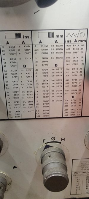
I looked at your photos again. There is no feed info on your front plate, only on the side plate. So I would assume the side plate is the correct configuration for feed info.

Why don't you just test it. Put your lathe in a gear where it's easy to turn the chuck by hand. Turn it till all the backlash is removed. Then index it and measure the feed travel per complete revolution of the chuck. Better yet, rotate it 10 times and then divide the total measured feed by 10. Compare that number to your chart.
 
Would the use of the 127 idler gear in the inch configuration yeild the same feed?

NO.

The feed chart specifically uses the 120/127 transposing gear. Feeds are only published for mm/spindle rev (long and cross).

Determining feeds in the Imperial system requires calculation - or determining them by measurement as @Susquatch is suggesting.

Personally, I would try and calculate them. There is some ratio between the lead screw and the feed rod. Once you have that, converting the TPI to feeds (both long and cross) is straight forward.

Edit: this is where the spreadsheet comes in… yes, you do need one because the data was not published for your reference in a manual or on a placard.
 
My questionning is that the side plate chart uses the 120T/127T gear while the front chart just uses the 127T gear as an idler. Will this influence the feed rates obtained on the carriage?
So if I put my levers in the E1 position, the longitudinal feed on the plate states 0.134mm (0.0053 in). Would the use of the 127 idler gear in the inch configuration yeild the same feed?
One way you can measure is to put the carriage in motion and measure the distance it travels over a set period of time and then compare the differences when changes are made.
 
NO.

The feed chart specifically uses the 120/127 transposing gear. Feeds are only published for mm/spindle rev (long and cross).

Determining feeds in the Imperial system requires calculation - or determining them by measurement as @Susquatch is suggesting.

Personally, I would try and calculate them. There is some ratio between the lead screw and the feed rod. Once you have that, converting the TPI to feeds (both long and cross) is straight forward.

Edit: this is where the spreadsheet comes in… yes, you do need one because the data was not published for your reference in a manual or on a placard.


My 1660 has the feeds in mm and inch. Might save some calculations
 

Attachments

  • 20230313_232626.jpg
    20230313_232626.jpg
    204.4 KB · Views: 13
Looks identical to the C0636 I bought from Modern tool in Calgary about 2004. Just different color paint and decals.
No quick change gearbox - always annoyed me to do any threading.
I'm going to make a suggestion here. Download the BB CX707 manual. Additionally search the Grizzly Tools site for the similar lathe. Download their manual it is likely the best version out there in terms of instruction as it is written in the USA and not a lose translation.
 
Sorry, I didn't read your question carefully enough. This might be one of those examples mentioned where they put metric feed chart on imperial machine. Why? It clearly says mm.
So assuming you are on power feed mode (as opposed to threading mode) I believe you could just make a substitute inch feed chart like so. Take the mm/rev value (red) divide by 25.4mm/inch = inch/rev (black). Looks like some have fewer significant figures than others, so there's that. I'm pretty sure I've worked this out backwards from known gears but not around that file right now.
I think this works for this lathe because whether its 127 or 120 tooth, its just an idler between the two 40T gears?

example for longitudinal feed
1678817674170.webp
 
I think this works for this lathe because whether its 127 or 120 tooth, its just an idler between the two 40T gears?

The trouble with that theory is the fact that the diagram to the left of the number you circled in your photo shows one of the gears engaged on the 127 and the other on the 120. If the diagram is right, it isn't just an idler.

There are simply too many variables going on here and too many assumptions. Many are mine. I've also misunderstood the question. I really think the best way forward is to test it at a few settings. It is easy to do and the results will clearly tell the story.
 
Here is what I would do:

Pretend I am threading 8TPI - 1B - (because the lead screw is 8TPI). Confirm that by engaging the half nut and turning the spindle by hand 8 revs and verifying that the carriage has moved 1 inch with a dial indicator.

Next I would disengage the half nut and engage the power feed on the Z-axis, and again turn the spindle by 8 revs and measure the travel of the carriage with a DI. Divide the DI reading by 8 ==> feed (in/rev).
Now you have a ratio of spindle rev to carriage travel using power feed. Confirm that ratio by selecting, say 16TPI on QCGB. It should take twice as many spindle revs to travel the same carriage distance.

Once you have the ratio, use a spreadsheet to convert all Imperial thread pitches to an equivalent feed rate for Z-axis (longitudinal feed).

The ratio of the Z-axis to X-axis can be either measured with a DI or computed from the Metric feed table on the side of the lathe.

Once you have that, again a spreadsheet will calculate the X-axis (cross feed) based on the longitudinal feeds.

On a lot of lathes, the Z to X axis feed ratio is 2:1; I think yours is something like 9:1 (the numbers are blurry in your picture).

You may find that a lot of the feeds you calculate are very closely spaced. I would pick maybe 12 or so from the table (a selection over its range) and try them out.

OR (as has been suggested already):

Find an equivalent lathe manual with all the charts already calculated.
 
I spent a little time researching metric threading on lathes and learned a few things. The only way I can remember stuff is if I write it down so here it is.

The most common lead screw is 8 TPI, a pitch of 0.125". That's 3.175 mm, not a convenient number from which to derive the standard metric pitches. The purpose of metric transposing gears is simply to scale that pitch into a more useful value that can be divided or multiplied, using common gear ratios, to get the standard metric pitches.
The traditional pair of transposing gears have 127 and 120 teeth. The lead screw pitch, 3.175 mm, multiplied by the ratio of those two gears, .945, gives us 3.0 mm, a much easier number to further divide or multiply into standard metric pitches. The important thing to remember is that using metric transposing gears allows you to treat your inch lead screw as a 3.0 MM metric lead screw. If you have a 127/100 tooth transposing gear it's like having a 2.5MM pitch lead screw
The example below shows 40 tooth gear on the output from the headstock and another 40 tooth gear on the input to the gearbox. A 100 RPM speed from the headstock produces 94.5 RPM at the gearbox.

metric conversion change gears.webp
 
Not the one I had, the 4 smaller knobs on the bottom just varied power feed speeds. Any threading, I had to take off the end panel and change out 3 gears (using 3 different wrenches), replace the end panel, cut threads then reverse the process to get power feeds back.
One of the 4 knobs controls feed or threading.
 
I spent a little time researching metric threading on lathes and learned a few things. The only way I can remember stuff is if I write it down so here it is.

The most common lead screw is 8 TPI, a pitch of 0.125". That's 3.175 mm, not a convenient number from which to derive the standard metric pitches. The purpose of metric transposing gears is simply to scale that pitch into a more useful value that can be divided or multiplied, using common gear ratios, to get the standard metric pitches.
The traditional pair of transposing gears have 127 and 120 teeth. The lead screw pitch, 3.175 mm, multiplied by the ratio of those two gears, .945, gives us 3.0 mm, a much easier number to further divide or multiply into standard metric pitches. The important thing to remember is that using metric transposing gears allows you to treat your inch lead screw as a 3.0 MM metric lead screw. If you have a 127/100 tooth transposing gear it's like having a 2.5MM pitch lead screw
The example below shows 40 tooth gear on the output from the headstock and another 40 tooth gear on the input to the gearbox. A 100 RPM speed from the headstock produces 94.5 RPM at the gearbox.

I always thought of it a little bit different and I think a little easier to both remember and get your head around. 1 inch = 2.54 cm. It is a standard definition. So 1/2" = 1.27 cm. Does the 1.27 look familiar? 100 x 1.27 = 127

A 100 tooth gear will turn 1.27 times when engaged on a 127 tooth gear that turns once. A perfect ratio.

There many other ways to look at it, but that's my favorite and I think it's the easiest to remember.
 
One of the 4 knobs controls feed or threading.

Both of your lathes are different to mine. Threading or feed is selected by levers on the saddle. The half nut engages threading, and the feed handle selects crossfeed or lengthwise or neutral.

All four of the bottom knobs select different gear ratios internally. Two have 2 gears each and 2 have 4 gears each.

The variety is amazing!
 
OK guys, here's a little hands on, chuck turning values mesured on my actual machine:
1678841287486.webp


Comparing these values to the ones that are on the plate of the change gear cover, here are the metric to imperial converted values:
GEAR COMBO: 40T - 127T/120T - 40T
1678841411868.webp


As far as I'm concerned, the values match up closely enough that using the converted metric values gets me close enough to the actual mesured values that I'm mesuring.
I'll call it a day :)

Thanks to all for the input and wisdom!
 
Just to add a thought using the information provided.
If the use of a combined 127T/120T provides a speed reduction from 100 RPM to 94.485 RPM, that means that the given metric values shoud be INCREASED by 5.8% (1/.94485) to match the imperial setup with only an idler gear.
Using this assumption, I took the supplied metric values, increased them buy the factor and compared them to my mesured values.
All bold red numbers are converted metric values that are within +/- 0.0005" from the values I mesured:
1678842849959.webp

I think we're on to something with these charts !!!
 
I'm convinced we have the identical lathe model because I have your exact charts in my manual. I thought I had this figured out once upon a time but I admit I was focused on threading. Nothing beats measurement as suggested but I want to understand the physical gearing in various modes. Unfortunately they don't provide all the puzzle pieces which is annoying.

So first the good news. I have an INCH feed chart on my lathe. Now the bad news, it has the same 40>127==120>40 gear arrangement shown. Why? I don't know.

1678848833719.webp


Which is where I go tripped up because the manual lays out the IMP 8TPI screw like this. Normal IMP mode is 3-gear train: 40>127>40, but you can also go 32>127>46 or 3>127>30 which would result in different net ratios to the gearbox. For metric threading on IMP leadscrew they show the 4-gear / common shaft / mid gear combinations and THAT is what they chose to show power feed numbers at.
1678848931902.webp


When they talk about the metric lathe version (3mm pitch) they show the arrangement like this. Now I just had a dark thought - are the gears in the Norton box the same between MET & IMP machines?
I smell smoke under my helmet.
1678849871645.webp

1678850403713.webp


When I made my spreadsheet it was mostly about threading on IMP leadscrews, validating the IMP & MET threads & figuring out other possible (even numbered) pitches they didn't include. I back-calculated out the gearbox ratio but that remains constant. But I think I can work out feeds from this information with any gear combination (...whenever my eyes become uncrossed).
1678849483695.webp
1678849738818.webp

1678849604849.webp
 
But I think I can work out feeds from this information with any gear combination (...whenever my eyes become uncrossed).

That was a great read Peter.

I feel your pain. I've never done what you did, but I'm gunna. I can smell smoke too and I have not even really started!

A question for you.

Why don't they list the 1, 2, or 6 lever positions for the 40/40 gear set? And why 6 for the 40/32 but not the 30/40. And why 2 for the 30/40 but not for the 40/32? I understand why they leave many squares blank, but why whole columns?

It would be kinda cool to find a 1.75 hiding in there and not have to make 2 gears.

To calculate the feed from the thread data, and assuming yours is like mine, all you have to do is determine the carriage gearing.
 
Why don't they list the 1, 2, or 6 lever positions for the 40/40 gear set? And why 6 for the 40/32 but not the 30/40. And why 2 for the 30/40 but not for the 40/32? I understand why they leave many squares blank, but why whole columns?
I asked myself the same question. One would think it would sell more lathes (and cause less ulcers) if they would provide a complete matrix of every permutation. Some lathes do, we have seen examples. Just not these guys or maybe this vintage. The more I dig into it, the more I realize what I don't know.
 
Back
Top