• Scam Alert. Members are reminded to NOT send money to buy anything. Don't buy things remote and have it shipped - go get it yourself, pay in person, and take your equipment with you. Scammers have burned people on this forum. Urgency, secrecy, excuses, selling for friend, newish members, FUD, are RED FLAGS. A video conference call is not adequate assurance. Face to face interactions are required. Please report suspicions to the forum admins. Stay Safe - anyone can get scammed.

How bad of an idea is it to cut structure out of my lathe base?

Robinhood I’d like to start today by saying
Me dumb you smart.
Thank you for coming to my TED talk.

Ok I never said I knew what I was doing, but I do an ok impression of it lol.

I’m more of a melt metal, power of the gods! fuse steel together mostly straight and/or square kind of metalworker. But I AM trying to be more refined

I went in the shop and was laying out bolt holes and space underneath, pics of the gear shifters etc.
Oh yeah the gear box that just “came with all the stuff” that I haven’t looked at in months.

Yeah it’s from the lathe. Ugh.

Could bolt right in. This is mind boggling to me. WHY would you want a dinky gear box then dual sized pulleys before your big massive gearbox built in the lathe?!
It’s got two different pulley sizes. Not sure how the heck you change the belt on it. Guessing there was a step pulley on the lathe at some point.

Gear box seems to have two speeds, but not sure the shape of them. What looks like it was a shift fork is missing, there’s a spring there, gently tried to move the gear and it didn’t want to move. I’m leaving that alone before I break it. The ratio is 1:1 1/8

It looks like the gear sets were welded to the shaft at some point also the coupler.

Started this post before I had to run out for a couple appointments and the belt tensioning was bugging me and I remembered as I was driving something in the box of junk I got with and there was a block with some sort of idler pulley on it.
This is finally starting to make sense!
A855C28B-E15C-4BFE-9782-E1C4C118906A.jpeg
025DA1AC-49A2-483B-BD15-CD36B3FC0513.jpeg
C9860695-5B93-4216-B144-DDF9B531E20C.jpeg
1A75D37C-6ACC-4A6E-92C9-A2601571443E.jpeg
 
No worries at all.

So all your 24 spindle speeds are achieved mechanically: 3 positions on the lever closest to the chuck (yellow, green and red), the 4 gated positions on the center lever, and the two positions (high, low) in the gearbox down below. 3 x 4 x 2 = 24, all speeds accounted for.

So you will be looking for a 3 hp motor whose shaft height is the same as the input shaft to the gearbox. Also, the diameter of the shaft is most likely the same as the shaft into the gearbox.

Based on these two parameters, using a table that has the “frame” specifics (see link), you should be able to narrow down the frame size required.


You will need a new love joy coupling with the spider - Princess Auto has a decent selection.

Yes, I see the “modifications” (welds) inside the gearbox. That is going to be tougher nut to crack…
I suggest you get a motor that fits and get the lathe going. You’ll have 12 speeds and a usable machine. You can then do more research and perhaps find a diagram of what the inside of the GB should look like and then repair it in the future.
 
It's starting to make sense now, to bad the gears are welded in place though. I'm wondering how the lower gear box was shifted as it would be a pain in the butt to open the access door each time you wanted a different range.
 
Yeah I’m sure I can make do with 12!
The set up is just odd to me.
And 2 gears and two pulley sizes so 48 speeds?

I think I can still use the gigantor motor it’s actually lower shaft hight then the gear box, should be able to shim it up with some 1/2 plate.


Getting stoked now! This might work!!
 
It's starting to make sense now, to bad the gears are welded in place though. I'm wondering how the lower gear box was shifted as it would be a pain in the butt to open the access door each time you wanted a different range.
My only guess is a cable pulled some sort of missing fork. There’s still a spring remaining. Def not a leaver
 
Sounds promising then that you can still use the big motor you have.

Maybe the quad groove sheave (2 pairs of different size) is reversible? If so, use the lager two when your motor is run at 50 Hz and the smaller two when you have 60 Hz available?

If this machine was made in Europe, they would have the 50 Hz motor installed and just gave a quad pulley when shipped to North America.

I think there is more stuff missing out of the gearbox than just the shift fork: it looks like those splines could have been part of a clutch pack which is now missing. There could have been an electro mechanical shifting device controlled by a push button on the front of the lathe. I am thinking of a HI - LO system like they have on a Graziano SAG 12.

This is pure conjecture on my part at this time and may be totally wrong… They obviously went to a great length of giving you 24 spindle speeds, plus, looking at all the speeds, feeds and threads your lathe has, they know how to build gearboxes - so would not put it past them to do such a thing.
 
It’s funny the lathe was made in Galt one of the three little town that make up Cambridge Ontario, it’s literally 10 minutes up the road from me! So the lathe came home so to speak.

The gears and feeds are awesome it’s WAY more of a lathe then I thought I would find. It even has a selection for metric or imperial threading built right in! I’d never seen that. The head stock of the lathe is cast aluminum also which I have not seen before.

As far as any electronics the only thing there is, is a hole in the front face I’m guessing was an E stop


As far as shifting I’m wondering if it had a push/pull type of cable as I found a similar bung type thing on the bottom when I flipped it to drain the old contaminated with chips gear oil.

It’s got a date with some break clean!

EAA00190-9789-4274-932B-1B59DB9BEFCB.jpeg

468EEC0E-4623-4A97-A518-6AD63880F354.jpeg
 
The head stock of the lathe is cast aluminum also which I have not seen before.
That sure is unique.

As far as any electronics the only thing there is, is a hole in the front face I’m guessing was an E stop
Yes, kind of an odd position for an E-stop.

Could be there is a bushing missing that would then allow a shaft to pass through to the rear and actuate the shifting mechanism. The shaft would have a long lever in a more or less vertical position in the front to allow the operator to shift Hi - Lo. Something like on a Cazeneuve lathe.

1639193191346.webp


As far as shifting I’m wondering if it had a push/pull type of cable as I found a similar bung type thing on the bottom
That is a very good observation. It means that you are missing quite a few parts of the mechanism then. The cables would need to be routed via pulleys and guides to the lever shaft that is coming in from the front of the base (the hole you see in the picture of your QCGB).
 
Another thought:

Is there a similar hole in the rear pedestal?

If there is, it is probably used for lifting. Push a close fitting steel bar through in both places and use two slings onto a crane hook and away she lifts.

1639193462682.jpeg
 
Ok bit of time this aft to continue working on this.

Cleaned out all the chips abs crap out the gearbox with break clean, industrial alcohol (I get tons) and compressed air. With one of the mint wire brushes you buy from PA but never really use cuz they’re too small, today’s your day little buddy!

Turns out beneath the grime there is a sight glass! One thing I’m wondering is the oil level is below the bottom of the lower shaft bearing, in input side I can’t see if it is an open bearing also but the gear bring so close it gets flooded with oil. The far side with the gear welded far away doesn’t get flooded, a little does make its way to the bearing, not sure if I should fill to the barring is covered.

Unfortunately The seals aren’t that great. Not sure how I’m going to
Tackle that since bubba abs his stick welder were here. I know if I put this in the lathe as-is it’s not going to come back out.


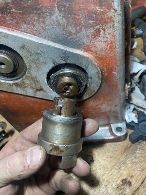
Wondering about this love-joy. I thought it was welded to the shaft but the weld of a larger diameter then the shaft. I don’t see why they would Machine a shoulder into the shaft that size. You’d have to turn the whole thing down.


There was a cap head bolt in the end of the shaft that didn’t thread into anything, but the hole was quite deep, was cleaning and spraying penetrant in the set screw hole and notice a cut in the bottom like a slot, I can see light through it. Now worrying about the strength of the shaft as I try and pull it.

However if I blow air in this hole I can see bubbles around the crappy weld.

I need to buy a smaller puller it see if I can get behind it, gentle prying off the case just moves the shaft.

Do I try abs pull it or grind out the weld and pull it off (which might let me change the seals/barring maybe)

Or just walk away find a compatible love joy and spider for the motor and call it good?


A436D355-163F-448A-9BC5-0CC02F356F78.jpeg
21E9F58E-DECC-4E5C-8128-9D30BE5E6EB1.jpeg
AC4DE1A8-F446-477B-851B-A2C103F90040.jpeg
6B5A3BBB-EE5A-4DAB-8565-5D829CA9C929.jpeg
7544E43D-CB74-4B62-AA46-9C21681AD0F2.jpeg
 
Could be there is a bushing missing that would then allow a shaft to pass through to the rear and actuate the shifting mechanism. The shaft would have a long lever in a more or less vertical position in the front to allow the operator to shift Hi - Lo. Something like on a Cazeneuve lathe.

Robinhood again with the big brain! I ment to snap a pic behind that hole, there are two pipe nipples side by each that go down into the storage shelves on the bottom of the lathe there is a cut out in the wall from there into the rear compartment near where the gear box is. It must have been for cables or something to run the gear box.

Good call!
Man I would love to find some factory info on this thing!
 
Man I would love to find some factory info on this thing!
That would make things a whole lot easier.

As far as oil level: the input shaft would turn at the motor speed (~1740 rpm), so there would be a lot of splash lubrication going on.

Once you clean the sight glass, you may find a level line - I would fill it to that. If no line, fill it half way up the glass. As long as there is at least one driven gear in the oil, it will pick it up and sling it around the gearbox.

I think the only way you’ll ever get the seals out would be to carefully grind off all the welds so that you can then remove the shafts, bearings and seals.

That may actually not be a bad plan, since you could then make sleeves for the shafts to locate the gears in the ratio you want - no welding required. And should you ever find info on what is actually missing, you could make the parts and reassemble relatively easily since you have no welds to fight with. Also if you find that you don’t like the ratio you have, change it to the more suitable one by sleeving the gears to the other one.

Looks like there is a retaining ring behind the welded LJ coupling.

If you find the bearings are still OK to reuse, yeah, just get the correct size coupling and give it a try.

Some manufacturers do sleeve shafts. It is sometimes used to retain a bearing after installation vs using a retaining ring. All depends on the design. And yes, in the “old days” it was not uncommon to take a shaft and turn it down to various thicknesses and shoulders. Most of the material was turned into chips if they just needed the one larger section - steel was cheap, or they did not want to skimp on quality…
 
So that is why they did that.

Not sure when or why but the shaft only sticks out from the shoulder a little less then 3/8 (.357)

The gap I could see though the setscrew hole was a gap between the shaft and an extension the made/built/repaired.

They tried to lock the bolt in with two set screws drilled in at 45° (ambitious I’ll give him that) but they drilled into the bolt weakening it severely. I think it broke and spun considering all the galling on the faces of the shaft. Then they just said F it and welded it (been there).

I had a tiny bit of hope when I modified a small puller to grab on the shoulder of the love joy and it seemed to move. I now know this was the shaft closing the gap, had to cut the weld to remove.

I would have left it on but the love joy and spider from princess (1.125 motor shaft) were larger then the 1” love joy on the gear box. The princess couplers are larger I won’t be able to weld to the shoulder like they have.

Do I mill off 30% of the lugs so it fits the spider, or cut the spider to fit the love original love joy and reuse it?

I’m not interested in rebuilding the whole shaft and shifter in the box. Would be cool to do if I had the time.

If I can reuse as is I can get to the job I need it for and keep my eyes open for a 3ph/vfd to replace this whole set up.

Who needs a drink?


44F9A1BA-96FE-4047-80B5-862C19226297.jpeg
D59EB889-EC46-4ED6-8F31-C7914B8E0E76.jpeg
48D6522F-E028-4CFB-8C96-408EA82C3F86.jpeg
C5B18783-D715-4820-BDAA-2619AF8E1B42.jpeg
 

Attachments

  • BE24EAE5-78FE-4E5C-B6E2-A3F7793E333C.jpeg
    BE24EAE5-78FE-4E5C-B6E2-A3F7793E333C.jpeg
    548.3 KB · Views: 3
They left you with a right old mess…

Looks like the shaft sheared off right where the key way ends - typical, it is a stress area.

Do I mill off 30% of the lugs so it fits the spider, or cut the spider to fit the love original love joy and reuse it?

Well, if you have a way to index the 1” LJ on your mill, you could reduce the width of the lugs to make them fit the 1.25” one. If you don’t, probably would be easier to trim the spider - I think you can buy replacement spiders at PA in case it does not work out (or it starts wearing quickly since you reduced its width).

If I can reuse as is I can get to the job I need it for

Agreed 100% - get it working and then do a proper repair/replacement later.
 
I don’t really have a way to index it besides a highly calibrated eye ;)

I like the spider mod as it will leave More bearing surface on the lj

I think I’ll mill a couple notches at the shoulder so I can weld in a little deeper.

If there was enough stress to shear the shaft I want a little more meat then a janky weld around the edge.
 
So the time for skilled machinists is out.

Time for redneck power.

I tig welded the stub shaft back on, then the LJ and welded it playing around to get the runout as low as I could, as the shoulder wasn’t concentric. This was fun as oil seems to make its was through this part. The tapped Center hole hits an opening inside I guess.

Break cleaner to degrease then weld and burst into flames. Rinse and repeat.

Then the seal issue, there is a general lack of them. Much worse then I thought. If I run it as is it will be dry in no time. Here’s where the redneck comes in.

Some rubber sheets, stainless and aluminum plate and I made external seals.
Are they going to last forever?
No
Will the improve it somewhat?
Maybe.
Will they make a real machinist cry? Oh probably lol

It’ll get me running and can work on the permanent solution later.

E5A81CDD-D480-425C-BF6B-7981190A4DEB.jpeg
BA3A1ACB-AF58-4E58-BBC9-1ADEAF8AB0F7.jpeg
49AB0AFE-B3D9-4899-969A-BD8235527DCB.jpeg
 
Oh the saga continues.

The motor isn’t working properly. Got off work early so figured I’d mock everything up on the bench before install.

Wired up the fed/rev switch that was still in the lathe, which would be nice to use. Switch in the OFF position, wires plugged into my welder plug, threw the breaker on an the lights dim and the motor lets out a loud buzz!

Double check the wiring and the OFF position of the switch. Matches the wiring diagram on the motor. Put my amp meter on and both sides showing over 80 amps! How it’s not tripping the breaker I don’t know, it’s a fluke meter so I trust it. Checked it on a grinder and it’s showing correctly.

I’m wondering if something is wrong with the capacitors or the wiring.

The motor wires are colour coded, but at some point in time were tagged with coloured electrical tape, maybe these tags are wrong?

Can anyone see how they could be wrong?

Ohm meter shows connections:

Yellow to capacitors
Blue to capacitors
Red to green
Black to brown

Wiring diagram

Green to line

Red
Black ———together
Blue

Yellow
Brown together——to line

Reverse swap yellow and blue Leeds
4D1DA925-8AFD-48E3-8642-0009E201C766.jpeg
image.jpg
image.jpg
 
Back
Top