• Scam Alert. Members are reminded to NOT send money to buy anything. Don't buy things remote and have it shipped - go get it yourself, pay in person, and take your equipment with you. Scammers have burned people on this forum. Urgency, secrecy, excuses, selling for friend, newish members, FUD, are RED FLAGS. A video conference call is not adequate assurance. Face to face interactions are required. Please report suspicions to the forum admins. Stay Safe - anyone can get scammed.

CT 043 issues ..... Repairs - Completed !!

You know I sent you a much better diagram in colour... I'll repost below.

There is a master switch too. But it is interlocked with spindle speed direction switches. I sent you a detailed post describing the order of the activation of the safety circuit that energizes the KA contactor and turns on the main power light. I can repost it if you can't locate the reply

View attachment 20522


View attachment 20523


View attachment 20524


View attachment 20525
The problem I have with the drawings you have sent is , It's not wired like that , some of it is nice to look at , however this one is different , this is the Grizzly ?

I downloaded the Drawing of the grizzly weeks ago , close but not the same either.
 
As a reminder owners of Grizzly and BB are brothers, just found out a few days ago that one of their machine suppliers is now one of their inlaws (BB side) :rolleyes:
Yes , I knew this a very long time ago , they are probably together celebrating Chinese new year as we speak.
 
This is exactly the same as what I posted..

The contactors are standard 220v 3 pole contactors with a normally closed auxillary contact, the only difference is grizzly accepts lower amperage specification. They operate identically and are merely made by a different manufacturer.


schematic-inside-electrical-box-jpg.19638

Did you look at the drawing I made ?
 
My apologies.

I had not previously looked at the diagram that you drew up. I just did now.

Fundamentally they are the same circuits... except that they use different numbering and they changed the order in which the wires make the connections, but they are still the same activation sequences. You did not include the wiring going to the safety switches but they all do the same sequences.

Case in point.... the low voltage wiring first passes thru the overload. Then goes to the A1 terminals of the contactors. Grizzly just takes a different path to do the same thing.

The diagnostic protocols remain the same... you can wire the connections using either pass. But you need to test the circuits the same way.
I have a rough drawing of the rest of it , the front panel , light , jog button , E stop
I have the spindle switches exposed so I can look at them and have drawn out that circuit as well .
Still working on the circuits for the wiring of the motor .
Once I have it finalized I'll make a nice drawing for keeps , To be kept in the manual .
I gotta say , having gone through this wire by wire has me understanding it much better and less head scratching.

A couple of things bug me about the drawing they provide in the owners guide is they do not draw all the wires as it is laid out inside the electrical box , is this to save ink ? .
I've never liked drawings done that way , the jerks that draw them think it's simplified and easier to read , not so much for me , I want to see all the wires .
Another thing that bugs me about this machine is not having a master power switch.
Also , it has several places where oil seeps , I should be used to that , having worked for years at a Harley Davidson Dealership.
 
The lathe does have a master power switch. It is the combined E-stop button and two interlocked spindle direction switches. They've chosen to think every user is an idiot that needs extra protection. I can't argue with that logic having seen what some people do with their lathes.

BB provides the drawing the way they do to merely show the control scheme. It is the simplest to represent, but unless you understand things well you have a hard time relating that to the actual wiring.
The transformer and the light on the front panel remain on constantly when the lathe is plugged in and the breaker is on , regardless of the E stop button. The transformer is warm to the touch when the power is on.
 
I might suggest that you contact the Concord office in Toronto. They still
Have some old staff that know their way around the old products (and they have some old parts stock).
I'll try , but I'm not gonna have any expectations that they might help , the manager in the store here , claimed to have talked to them and said there was very little they could do for me with "such an old machine" , her sourness made me bitter.
 
Here is another site with the same lathe and issues and the solution.


I have had motor issues on my mill twice, both time motor contact wiring inside the motor. First time loose wire, second time melted contactor block (second was replaced with a used block odd size from my motor shop and this started me down the road to VFD and ultimately CNC).
 
My apologies.

I had not previously looked at the diagram that you drew up. I just did now.

Fundamentally they are the same circuits... except that they use different numbering and they changed the order in which the wires make the connections, but they are still the same activation sequences. You did not include the wiring going to the safety switches but they all do the same sequences.

Case in point.... the low voltage wiring first passes thru the overload. Then goes to the A1 terminals of the contactors. Grizzly just takes a different path to do the same thing.

The diagnostic protocols remain the same... you can wire the connections using either pass. But you need to test the circuits the same way.
So , looking at the Grizzly wiring and then looking at the BBT wiring as shown on the label inside the door on my lathe and then looking at the motor wiring I actually have ............
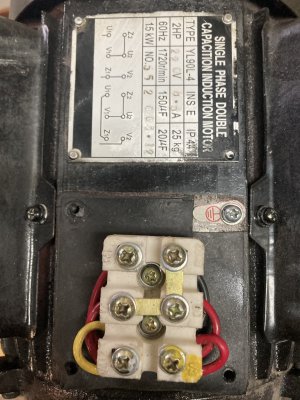
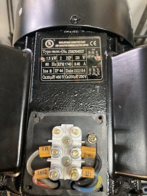
I see an additional wire that my machine doesn't have , Both the Grizzly and the BBT drawing have a U1 wire that connects to N , giving the motor wiring four wires plus the ground .
My machine does not have that U1 wire , it has a Z1 , U2 , Z2 and the ground , I brought this up quite a while ago .
 
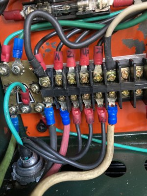
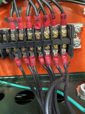
Here's a pic , showing of the terminal strip . The power coming in from the wall outlet along the bottom is the ground , black & red wires , there is a 110 outlet I put on the side of the machine for a work light and a coolant pump that I never did add , that's why there's a Black and a white wire coming off the terminal strip on the upper row of terminals.
The motor wires are the three between the red wire and the white wire on the lower row.

My question to you is , should my motor have three wires or four ? , it's always had the three shown here .

Oh , and thank you for reminding me that I'm " lacking fundamental understanding of motor operation" , I've said it before , several times , this is not my area of expertise .

IMG_1371.JPGIMG_1370.JPG
 
Last edited:
In the process of working my way through this I was not pleased with the wiring diagram provided by BBT , it pissed me off , I do not think clearly when I'm pissed off.
This is the one in the owners manual , Fig 8 "Electrical Principium " is what they call it , what a joke !.
View attachment 20518

This is the one inside the electrical box , on the door .

View attachment 20519
The drawings above are almost useless , anyone who has purchased a CX707 is on their own to figure any of this out.
There's no master power switch , for over 18 years , I've been just plugging it in and using the breaker to power it up. There's so much missing from both of the diagrams they provided , I was confused from the start , I always thought I had a good handle on electrical , well , automotive / mobile equipment / low voltage systems anyways.


I've made my own drawings , this is the only way I can get my brain around how this thing is wired . I'm working on a second diagram , detailing the "e" stop , power lamp , jog button & the switches on the carriage . In my day to day activities as a mechanic , it's how I have been able to successfully complete repairs , by having an actual wiring diagram to work with. The wiring diagram inside the door and in the owners manual are not even close to being helpful .

View attachment 20520
Sorry to add to the suggestions but if you take the live and neutral off were they come in on the bottom left of your drawing at the over load device and take the live and neutral off at the transformer and replace them with the two you took off first in my recollection you would still power the contactors and could safely measure across the contactors first with voltage to make sure there is none and then test for continuity across your contactors both energized and deenergized, de energized should be no continuity and energized should be continuity.
 
Sorry to add to the suggestions but if you take the live and neutral off were they come in on the bottom left of your drawing at the over load device and take the live and neutral off at the transformer and replace them with the two you took off first in my recollection you would still power the contactors and could safely measure across the contactors first with voltage to make sure there is none and then test for continuity across your contactors both energized and deenergized, de energized should be no continuity and energized should be continuity.
We've kind of already established that I have a bad contactor so what you are suggesting really isn't a test that is necessary at this point , the guts of this thing is on the bench right now .
 
Despite the fact you admit that this is not your area of expertise you continue to question those trying very hard to help you.

asked and answered. Your motor requires just two leads to operate, but just 3 leads to have the contactors do the work of changing the rotation.
The reason I ask questions is .....
What is shown in the Grizzly drawing is clearly showing a four wire motor setup , the picture of the terminal strip shows four terminals feeding the motor inside the electrical box , the illustration of the motor shows four wires & the ground.
The drawing inside my electrical box shows four wires but it only has three actually going to the motor & the ground.
 
Last edited:
Back
Top