SparWeb
Active Member
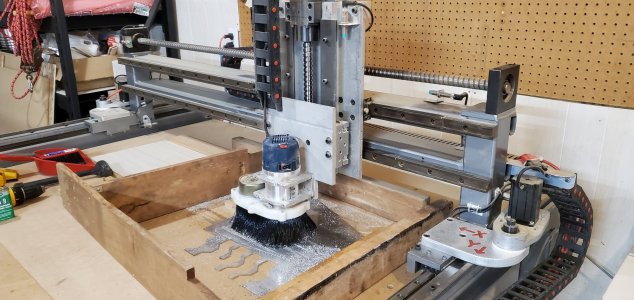
Still getting my CNC router dialed in.
Thanks to many forum members, for your help so far.

 canadianhobbymetalworkers.com
With some free time over the holidays, I set about making sure it's well calibrated. Mostly it seems to be OK, but sometimes it isn't. I am still trying to figure out what's going on.
The big picture is this:
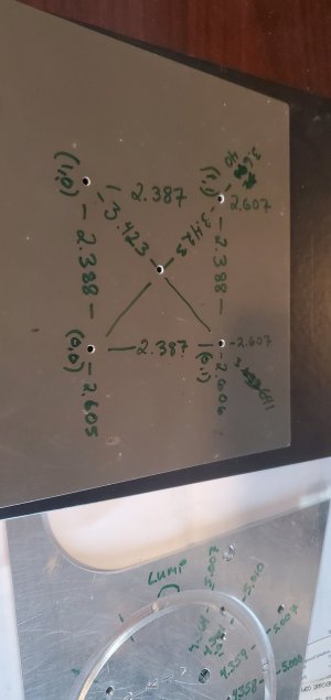
- When drilling, it's bang-on, or as close as can be expected with 0.002" or 0.003" backlash on each axis.
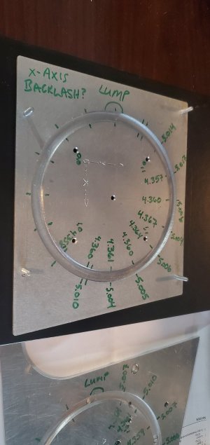
- When profile cutting, it's all over the place. Circles are oval by 0.014" in places.
The lumpiness makes the circles "egg-shaped" and rotated by 45 degrees. I thought this was backlash on both axes but it doesn't add up.
I have been cutting circles as profile cuts in aluminum plate. The 1/4" cutter is doing passes only 0.03" deep so it takes 2 passes to cut a circular trench 1/16" deep. The 2 passes coincide exactly. The trench is a bit wider than the 1/4" cutter so it makes separate passes to cut the OD and the ID of the trench. Climb milling all the time, except for the lead-in ramp which is just the way VCarve always does it. I measure the diameter of the trench's OD and ID at various angles around the circle.
The lumpiness of the circles has some definite patterns. I thought I could trace it back to things like backlash, but the backlash isn't that bad (I think). If I try to do the math on the way the backlash could alter the circle, then advancing in one direction could put in +0.003" on that axis, and +0.003" on the other axis. That would make the circle egg-shaped (according to Pythagoras) by only +0.004", not 0.014". I did one of my test cuts by conventional milling direction, and the lobes didn't reverse like I expected. The cumulative error is about the same either way.
To measure the backlash, I used a dial indicator and ran each axis back and forth, measuring the position when the carriage moved to the indicator versus moving away. That's how I got 0.002" on the X and 0.003" on the Y. This isn't enough backlash to account for the oval circles. If you think I'm measuring backlash wrong, I'll post some photos of this set-up so that you can point out any problems.
One more hint: The point where the cutter leads into the plate doesn't seem to be correct. The trough should be a perfect circle, but where the cutter leads in you can see the circle flattens out a little. The path in VCarve looks curved, and the G-code definitely has a lot of X/Y points strung together along the lead in path. This suggests something else is going on. Another hint that I've underestimated the backlash? Flexible cutter?
Side note: The head seems to be nicely trammed in because the bottoms of slots are very smooth and don't have ridges between passes. So I don't think it's that - or is that assessment too hasty?
Thanks to many forum members, for your help so far.

Motor Acceleration between Master & Slave
Hello, I've been enjoying my CNC router table since getting it several months ago. The holidays have given me time to try some more ambitious projects, and get tighter tolerances on parts. I knew this is when limitations or problems would show up, but no disasters so far...
 canadianhobbymetalworkers.com
With some free time over the holidays, I set about making sure it's well calibrated. Mostly it seems to be OK, but sometimes it isn't. I am still trying to figure out what's going on.
The big picture is this:
- When drilling, it's bang-on, or as close as can be expected with 0.002" or 0.003" backlash on each axis.
- When profile cutting, it's all over the place. Circles are oval by 0.014" in places.
The lumpiness makes the circles "egg-shaped" and rotated by 45 degrees. I thought this was backlash on both axes but it doesn't add up.
I have been cutting circles as profile cuts in aluminum plate. The 1/4" cutter is doing passes only 0.03" deep so it takes 2 passes to cut a circular trench 1/16" deep. The 2 passes coincide exactly. The trench is a bit wider than the 1/4" cutter so it makes separate passes to cut the OD and the ID of the trench. Climb milling all the time, except for the lead-in ramp which is just the way VCarve always does it. I measure the diameter of the trench's OD and ID at various angles around the circle.
The lumpiness of the circles has some definite patterns. I thought I could trace it back to things like backlash, but the backlash isn't that bad (I think). If I try to do the math on the way the backlash could alter the circle, then advancing in one direction could put in +0.003" on that axis, and +0.003" on the other axis. That would make the circle egg-shaped (according to Pythagoras) by only +0.004", not 0.014". I did one of my test cuts by conventional milling direction, and the lobes didn't reverse like I expected. The cumulative error is about the same either way.
To measure the backlash, I used a dial indicator and ran each axis back and forth, measuring the position when the carriage moved to the indicator versus moving away. That's how I got 0.002" on the X and 0.003" on the Y. This isn't enough backlash to account for the oval circles. If you think I'm measuring backlash wrong, I'll post some photos of this set-up so that you can point out any problems.
One more hint: The point where the cutter leads into the plate doesn't seem to be correct. The trough should be a perfect circle, but where the cutter leads in you can see the circle flattens out a little. The path in VCarve looks curved, and the G-code definitely has a lot of X/Y points strung together along the lead in path. This suggests something else is going on. Another hint that I've underestimated the backlash? Flexible cutter?
Side note: The head seems to be nicely trammed in because the bottoms of slots are very smooth and don't have ridges between passes. So I don't think it's that - or is that assessment too hasty?


