• Scam Alert. Members are reminded to NOT send money to buy anything. Don't buy things remote and have it shipped - go get it yourself, pay in person, and take your equipment with you. Scammers have burned people on this forum. Urgency, secrecy, excuses, selling for friend, newish members, FUD, are RED FLAGS. A video conference call is not adequate assurance. Face to face interactions are required. Please report suspicions to the forum admins. Stay Safe - anyone can get scammed.

Other Basic Electronics, Multimeters, & Oscilloscopes

This thread is about basic electrical, electronics, Multimeters, and Oscilloscopes. It is an outcome of interest that various members have expressed about these subjects.

@Janger , @Johnwa , and @kevin.decelles have all recently obtained a starter Oscilloscope so I think the timing is good for a thread like this.

The primary resource will be a book (available on Amazon in paper or kindle) called Electronics for Dummies by Kathleen Shamieh. The book isn't a requirement, but it always helps to have a reference of some kind to facilitate discussion. Other references might get added as the thread progresses.

I'm not picturing this thread as a course, just a good place to ask questions, find answers, and share knowledge and experience about basic electrical knowledge and testing.

As always, a good time and lots of great jokes are expected!
 
Based on what I've seen in 4 of 5 treadmills I have acquired lately, the tach input could be something as simple as a reed switch. I'll plan to verify this. Does it make sense that the controller is expecting that input?

It looks like the “tach” input is a magnetic reed switch so the input is switch closed once per rev, in this case rev of the driven sheave.

Whether that’s the case for the PA board is TBD.

EDIT: I should have said that I verified the reed switch this afternoon while playing with one of the sets of hardware.

D :cool:
 
Last edited:
I went to the south princess auto and they were sold out if that will save anyone a trip out there.
 
Sometimes strange things happen.....

This is a very necessary popular science tutorial, I love it! Although I may not have the time or energy to learn its complex functions in depth, simple measurements are still very useful techniques.

The reason why I don't want to study deeply is that it requires too much time and energy. And I don't want to dabble too much in the electronics field, I like the mechanical structure more. It just so happens that I have a very powerful electronics friend who can help me with most of these convenient problems.

Thanks to Dad for his extensive technology popularization!
 
Last edited by a moderator:
Other than smoke being bad, I'm pretty clueless about electronics but here goes.
I bought the same DC motor controller as Ian.
Hooked up the power to L1 and L2.
Hooked the motor to M1 and M2.
Wired the 5k pot to P1, P2 and P3.
Other than a click on the relay when I plug it in, nothing.
I know the motors work, tried 2 of them. The will both spin with a 20volt Dewalt battery. Both motors are around 2 hp treadmill motors, one is 90VDC one is 120VDC
When I test across the M1 and M2 I get 27 volts no matter where the pot is set.
One motor has the temp overload wires so I hooked it up to T1 and T2. No difference.
Suggestions or smart ass remarks are both welcome.
I find ridicule to be a strong motivator.
I am also an electronic idiot, but I still have my own learning experience, hoping to help other electronic white.

I remember when I first started using the frequency converter (VFD), I was extremely confused in the face of the simplest parameters, and could only rely on mechanical recording to force memory. And can only carry out the simplest frequency adjustment, and then constantly look at the manual, constantly try to debug parameters to learn the difference of parameters.

Then read the instructions after a while, and then debug - you will find that many things become easier to understand.

I now use more Siemens M440 inverter, I found that after you use more, the manual becomes simple, although we can only use its powerful function proportion is still relatively small, but it has been able to meet my machine tools, equipment running almost all functions.

For example: I used it to drive the spindle motor of the JUNG grinder, and I relied on learning instructions to activate the function of a frequency converter to control the two-speed motor.

So as long as you keep switching between the actual operation and reading comprehension instructions, you will learn to use it faster. I hope my clumsy methods can benefit some people.
 
Good day, I'm looking for a bit of advice on hall sensors and RPM displays.

Question 1, for an NPN, 3 wire, Normally Open type of hall sensor like the NJK-5002C as found on Aliex:


and as part of an RPM display:


is the output I should expect a +5V(?) square wave at the black wire? Why does the simple circuit diagram show the black & +V line "connected" with the square/diagonal line block?

If I wanted to replace the hall sensor with the output of a simple reed switch and drive the display module would I have to provide a +5 source to send to the (black) input to the display or could I just use the +V from the display and use the reed switch to relay it back to the display?

Why am I asking these questions? I have the sensor/display unit and I'm trying to measure the slowest speed on my brushed DC motor conversion on my drill press and I'm not satisfied with the RPM I'm getting from the display, it's unstable which may be just because it's a cheap Aliex thing but since I have it I'm experimenting a bit.

I do not have access to a "proper" PA RPM sensing tool but I was contemplating using my O-scope to figure out the frequency of the signal, I think that would be about 3.3 Hz/200 RPM.

Your thoughts & suggestions would be appreciated!

Thanks,

D :cool:
 
One aspect of the ali switch is the supply voltage needs to be higher than 6 volt. If it’s below 6 volt the sensor will be very unstable and slow to react to the magnet. 12 volt works best.

The black wire is switched, goes to ground-ish when the magnet comes within range.

A reed switch is tricky, they won’t react fast enough to read anything over about 1000 RPM. 1000 RPM is 16 hz, means the reed switch needs to switch faster than 60 ms, and not bounce.

I just checked my tach (same as the ali express except 110 volt), and the brown wire is at +11 volt, blue wire is ground, the black wire outputs a 7 volt signal that goes LOW (0.5 volt) when triggered by the magnet. I get reliable readings from 30 RPM to 2000 RPM (the fastest my lathe will spin)
 
I have the 110 - 220V version as well. I think I’ll have to drag out the ‘scope & see what the output looks like. Are you using a single magnet?

Interesting to note the reed switch. Typical treadmills including the donor for my mod have reed switches that sense the RPM of the belt drive. I know this one is working because when I added a second magnet to trick (test) the Hall effect sensor by doubling the counts, it reduced the RPM of the motor to compensate! Interesting to know to adjust speed but not what I was trying to test.

The end game right now is not to just have an RPM display but to determine the actual RPM so I can label my multi-position switch that replaces the treadmill 1 - 10 speed buttons. Once that is done the display is redundant.

D :cool:
A single magnet.

Quick-n-dirty math. The treadmill belt is moving at maybe 10 mph, 52,800 ft per hour, or 73 inches per second. The belt roller is about 2 inches in diameter, so about 6 inches in circumference. So the reed switch is tripping at highest speed at roughly 12 Hz, or 720 rpm.
 
A single magnet.

Quick-n-dirty math. The treadmill belt is moving at maybe 10 mph, 52,800 ft per hour, or 73 inches per second. The belt roller is about 2 inches in diameter, so about 6 inches in circumference. So the reed switch is tripping at highest speed at roughly 12 Hz, or 720 rpm.

After some fiddling this evening I got the sensor to give fairly steady readings with the slowest speed being about 180 RPM or about 3 Hz for the 1 MPH setting. I was also able to get to the highest RPM of about 1600 for the 9 MPH setting. The treadmill RPM is measured at the driven (walking belt) pulley which has the magnet mounted at about 4" dia. I've also swapped the drive sheave size down by maybe a factor of 15% so the actual MPH calculation would be compromised but it's not important for the application.

I managed to get the RPM display to run more or less stably by carefully aligning the sensor perpendicular to the magnet at a very close distance. I had bought another sensor (same P/N) in case I wanted to instrument another machine and I tried it with the display but it would only offer an overspeed indication. It did clearly show sensing/switching via the LED on the sensor so I don't know at this point why it did not communicate correctly with the display. The sensor that came with the display has an LED also but it doesn't work......

I was able to see pulses from both sensors using the o-scope although I was not satisfied with what I was able to display, probably my fault. I was hoping to be able to count pulse timing with the 'scope.

Last up I'm contemplating re-balancing the treadmill sheave/flywheel because on the highest RPM settings it displays a fair amount of vibration........that could be an adventure.

D :cool:
 
Last edited:
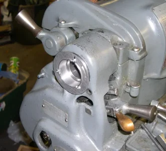
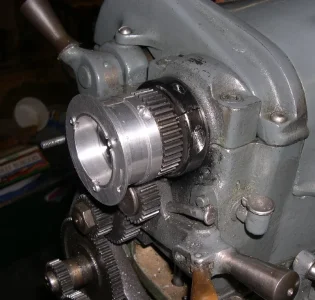
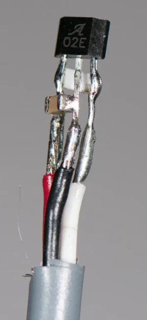
This was one approach I investigated for creating a Single Pulse Per Rev on my South Bend.
1699679078405.webp
This hub held the disk with the slot and left a hole for the collet draw bar.
1699679152476.webp
Here it is with the cover removed.
1699679272481.webp
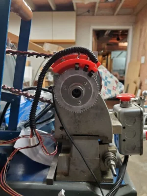
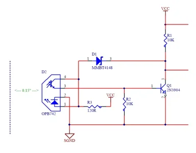
The Gingery lathe has small metal disk behind this bigger one with one slot for 1PPR for the ELS. As yet I haven't used the 3D printed assembly with three slotted sensor for LinuxCNC. The slotted sensors aren't expensive and are even salvageable from old printers.
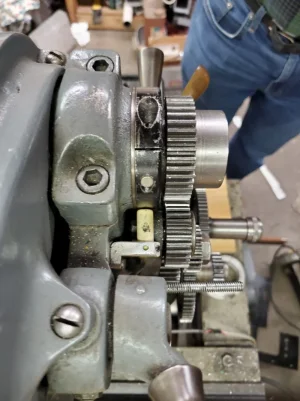
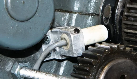
For the South Bend I eventually embedded a magnet in the end collar clamp hole and epoxied in a hall effect sensor into a small plastic tube.
1699679798637.webp
This again gave 1PPR with great rise and fall time. I think the magnet came from Lee Valley Tools as a set of 10 magnets.
 
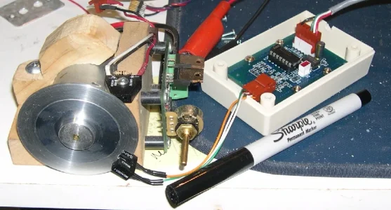
Or reflective sensors.
1699683375127.webp
Here's a test rig I used a number of years ago. Variable speed on DC motor. Both slotted and reflective sensors. The little board takes the singled ended pulses and translates them to RS422 differential for noise immunity. Never did use those. Still sitting in a box.

1699684378054.webp
 
Time for an update.

I played around a bit more this morning and discovered that by moving the sensors away from the head bearings/quill the display became more stable and the second sensor now works as well as the original. Not completely stable but good enough to think I’m getting useful RPM data.

For testing the magnet is taped to the aluminum driven pulley Away from the bearings and the sensor is on my nauga DTI mount.

Filling in some of the data, I see 11.8V at the brown wire and ~7 at the black except when it goes low/signal.

I wasn’t able to get what I wanted (RPM) from the o-scope, maybe I have something to learn there, lol!

I am now contemplating piggybacking on some of the recent discussion about balancing grinding wheels to have a go at the balance of the drive flywheel….

D :cool:
 
Last edited:
Just filling in a bit of what might hopefully be useful information:

I think those PA laser tachs are crap. I have one. I bought it when I couldn't find my old mechanical tach. But with suitable care you can actually make the PA unit work. If you wrap the spindle in black tape first and then add the reflective tape, it improves the contrast and helps stabilize the reading. It also helps to make sure the reflective tape is wide enough to catch the entire laser beam (which isn't well collimated). I also found the distance to be critical - about 6 inches. And sometimes turning the unit on its side helps so the beam is turned 90 degrees. But you still have to be cautious about it and make your own decision about how good the reading is. There is no good reason for it to be so bad. It ought to be a good gadget.

I got a mechanical tach from a member to replace my old one. It is foolproof. Oddly, my old one didn't turn up the day the replacement arrived. It seems to be gone forever. A mechanical tach provides a good collaboration of the electronic units. You just have to make sure the input shaft turns reliably with whatever it's placed on, use a stopwatch, and do some math. Otherwise they are absolutely foolproof.

Using your oscilloscope ought to be bullet proof if you can get a stable display. I don't know your scope, but most likely, you are right about it being a trigger issue. Sometimes reversing the trigger polarity helps. But noise will F#&@ it up and make the display jump all over the place. Sometimes you can filter that with a small RC circuit between the scope and the sensor circuit. Other times, a better circuit is required. Once in a while it's better to just give up and take a different approach.

A reed switch is only good at low speeds and won't provide good long life. But I think you know that already.

Good stuff figuring out that proximity to the bearing was a problem. I loved your temporary use of the Noga holder and some tape for the magnet. It makes me realize I need to test my own planned setup before I invest a lot of time in machining of all the parts. I have a thread on it somewhere but my idea was to use ABS collars to hold the magnets.
 
A little humour and a measure of dumbness. I fitted an RPM counter, from Amazon, on my mini-lathe, superglued the magnet onto the spindle and fired it up. Something was not right, the display gave all sorts of strange characters that changed with the spindle speed. It was a while before I figured out what was wrong with it, I was viewing it upside down:oops:
I do want to put an ampmeter on it though, these little lathes typically blow the breaker at 10 amps or so so it would be nice to see when I'm approaching the limit.
 
I do want to put an ampmeter on it though, these little lathes typically blow the breaker at 10 amps or so so it would be nice to see when I'm approaching the limit.

This is an interesting question. The bigger lathes usually hit their max current at startup. The huge inrush of current required to get them going against all that gear inertia blows the breaker.

I am guessing that isn't an issue with the little guys. But unlike a big lathe, which might not ever see full load in its lifetime, except at the highest rpm, a little lathe might see full load quite regularly.

I'd like to see that current profile too!
 
Just filling in a bit of what might hopefully be useful information:

Using your oscilloscope ought to be bullet proof if you can get a stable display. I don't know your scope, but most likely, you are right about it being a trigger issue. Sometimes reversing the trigger polarity helps. But noise will F#&@ it up and make the display jump all over the place. Sometimes you can filter that with a small RC circuit between the scope and the sensor circuit. Other times, a better circuit is required. Once in a while it's better to just give up and take a different approach.

My ‘scope is an ancient Telequipment Type S54 if that means anything:

IMG_20231112_153436892_HDR.jpg

Settings suggestions? Let's assume I'm trying to catch a 7 Volt, 3 Hz square wave for about 180 RPM. About 2V/cm & 200 mS/cm?

When you speak of a small RC circuit are you speaking of a series resistor (value?) with a small (a few pf) cap between the signal side of the resistor and ground?


A reed switch is only good at low speeds and won't provide good long life. But I think you know that already.

I understand the reed is a mechanical switch subject to wear but I’m scratching my head on this one because that’s what most of the treadmills use for their Tach input. Designed to price point? Maybe they aren’t designed to get that much use over their lifetime or maybe it’s a planned service revenue stream.;)

Surfing just for curiosity, I see reed switches spec'd to hundreds of millions of cycles at low voltage and switching speed to 1 - 2 kHz. Maybe that's not for treadmill quality parts though!

Good stuff figuring out that proximity to the bearing was a problem. I loved your temporary use of the Noga holder and some tape for the magnet. It makes me realize I need to test my own planned setup before I invest a lot of time in machining of all the parts. I have a thread on it somewhere but my idea was to use ABS collars to hold the magnets.

Base on my limited experience you do indeed want to mock up your installation before spending any time designing and making in-machine mounts. From what I hear, it also pays to mount the display right side up for the test.;)

I can’t guarantee that a genuine Noga mount will work, I used an imitation Nauga from PA, I’m not sure that stood out in my description. :p

D :cool:
 
Back
Top