• Scam Alert. Members are reminded to NOT send money to buy anything. Don't buy things remote and have it shipped - go get it yourself, pay in person, and take your equipment with you. Scammers have burned people on this forum. Urgency, secrecy, excuses, selling for friend, newish members, FUD, are RED FLAGS. A video conference call is not adequate assurance. Face to face interactions are required. Please report suspicions to the forum admins. Stay Safe - anyone can get scammed.

Unknown Mill

Payner

Active Member
Premium Member
This is a project that I'm still working on .
Appears to be a Craftex CX603 ( current model ) , there is no name on it just a serial number stamped under the table and a decal under the belt cover indicating spindle speeds .
I don't know any history on the machine as I bought it from a school board auction, apparently it went thru one auction and wasn't purchased so I picked it up for scrap price .
It had NO electronics with it but it has ball screws on all 3 axis and 3 stepper motors as well as a 1 HP , 90 volt DC motor for the spindle . It appears to have been originally a CNC machine as there is no quill feed or quill lock and the quill lock hole isn't even bored . It is an R8 spindle .
I had a DC drive control so that is now working .
I found an article on the net for making variable speed / reversible controls for the X , Y ,Z axis so they are powered up . I'm not interested in making it CNC but at least the drives are powered .
I use a computer power supply for the electronics and the steppers are powered by 3 separate 30 volt power supplies.
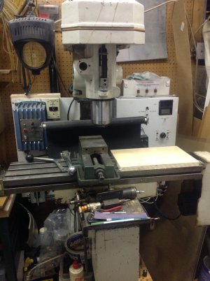
image.jpeg
Machine at present

image.jpeg
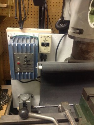
90volt power supply and Bijur style oiler
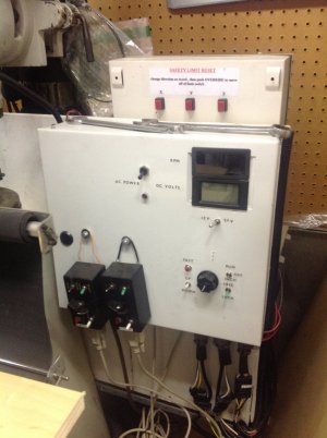
image.jpeg
Stepper motor controls and pendents

image.jpeg

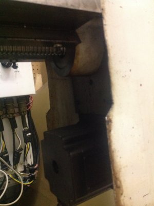
Ball screw and stepper motor .

I also have a millrite mill , south bend lathe , converted wood to metal bandsaw and a surface grinder that I'm just starting on .
Bill
 
This is a project that I'm still working on .
Appears to be a Craftex CX603 ( current model ) , there is no name on it just a serial number stamped under the table and a decal under the belt cover indicating spindle speeds .
I don't know any history on the machine as I bought it from a school board auction, apparently it went thru one auction and wasn't purchased so I picked it up for scrap price .
It had NO electronics with it but it has ball screws on all 3 axis and 3 stepper motors as well as a 1 HP , 90 volt DC motor for the spindle . It appears to have been originally a CNC machine as there is no quill feed or quill lock and the quill lock hole isn't even bored . It is an R8 spindle .
I had a DC drive control so that is now working .
I found an article on the net for making variable speed / reversible controls for the X , Y ,Z axis so they are powered up . I'm not interested in making it CNC but at least the drives are powered .
I use a computer power supply for the electronics and the steppers are powered by 3 separate 30 volt power supplies.
View attachment 17245
Machine at present

View attachment 17246
90volt power supply and Bijur style oiler

View attachment 17247
Stepper motor controls and pendents

View attachment 17248

Ball screw and stepper motor .

I also have a millrite mill , south bend lathe , converted wood to metal bandsaw and a surface grinder that I'm just starting on .
Bill

Wow Bill good project.

Tell us more about how you control the axis. I see the pendants. Do you have a dro? Without handles and scribed distances on the wheels or a dro how do you move the axis precise amounts?

That does look like a cx603 I used to own one. But that machine did not come with ball screws or a DC spindle. Sounds like a shop teachers project that never got finished. Glad you are keeping it going!
 
John . Thanks for the comment.
Here is a link to the site where I found the circuit

http://www.haythornthwaite.com/119 More Power at Your Elbow Electronics.pdf

I made 3 of them , the X and Y are on the pendents so I can hand hold them when needed and the Z is on the control panel , I figure that once I get the quill working I'll only need it for rough height adjustments .
When the movement is in the free mode it can be moved by hand , hoping to put handles on the X and Y axis .
When in the lock mode it won't move when cutting.

I have found that most CNC steppers use a 3:1 reduction , I'm guessing for accuracy or torque where my setup as bought is 1:1 . I'm going to have to look into this and probably change .

So far I've only made a couple of light cuts on aluminium to check operation and used a dial indicator for movements .

I plan on installing DRO's in the future, I have that setup on my millrite going through Yuro's toys touch DRO .

There was cutting fluid on the machine when I got it so I'm assuming it was used at some point and not sure what happened to the electronics , unless they crapped out or where taken off for another project .
 
Cool machine, one think I would like to mention is that ball screws do not work well with hand wheels. The issue is that ball screws have low friction and a the thread lead is very high. This would mean that the table will want to move when cutting unless you lock it somehow.
 
Cool machine, one think I would like to mention is that ball screws do not work well with hand wheels. The issue is that ball screws have low friction and a the thread lead is very high. This would mean that the table will want to move when cutting unless you lock it somehow.

Thank you for that information , I know that if using the X axis you typically would use a mechanical lock on the Y and Z axis . I had thought about using the " lock " feature on the control panel which I think should provide a similar result .
 
Two of my friends in Calgary with 10X54 mills use ball lead screws, on totally manual machines. They do not have any problems. The perception is that the not cranked axis will 'walk away' from the force of the cut. It can, but doesn't have to.

One of them always locks the unused direction, they other guy doesn't care, and it works for him.
 
I found a couple of pictures of the sub assemblies
image.webp
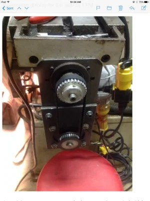
Notice the cog pulleys are 1:1 ratio , most CNC machines 3:1 ratio . Something else to investigate and change .

image.webp
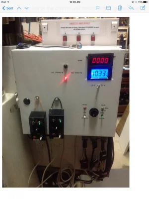
The panel powered up , the computer power supply is on the back side of this panel in a mini computer tower . The green item on top of the panel is the sending unit for the tachometer.

image.jpeg
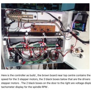
The 3 power supplies for the stepper motors are also in the computer tower on the backside of the panel .
 
Two of my friends in Calgary with 10X54 mills use ball lead screws, on totally manual machines. They do not have any problems. The perception is that the not cranked axis will 'walk away' from the force of the cut. It can, but doesn't have to. One of them always locks the unused direction, they other guy doesn't care, and it works for him.

I know you & I have chatted about this very same thing. I never did find the old link I read where someone did the conversion and he had a 'drifter'. I can't even recall what kind of lathe he converted or if lack of lock was a contributing factor. It seemed like just a great idea at the time but he basically had to undue it. Then I saw a subsequent conversion link on a mill I believe where it appeared to work just fine but I recall the post basically ended after conversion, no real operational commentary.

But I got thinking about this - do you think another factor is the pitch of ball screw assembly? ie. they selected a coarse pitch ball screw maybe intended for rapid transit or whatever reason & that was reason for being problematic? Whereas a finer pitch ball screw is maybe OK? I'm guessing some of selection criteria would be fine enough pitch so its kind of like (or ideally matching) dial gradations/resolution of the stock machine. I don't know much about sizing/availability. It would be interesting to get to the bottom of this issue because it seems to me there are scads of cnc ballscrew kits available whereas conventional leadscrews & ABL nuts are getting to be slimmer picken's. It would be a great way to make an old machine new again.
 
Absolutely the pitch matters! I can check out Fred's mill and see what his pitch is. I think there are a few other factors or the top of my head: quality of fit, size (weight) of mill table, how tight the gibbs are adjusted, etc.

These are large mills, 10X54 with tight gibbs and very high end ball screws.

A ball lead screw may well drift in some (or many) installations, I just wanted to say that it doesn't always have to.
 
My table is 7" X 30" and there is no mechanical lock or I can't see where one would go , will have to check the Craftex at Busy Bee next time I'm in town .

I'm only guessing it's a Craftex .

Using the stepper locks on the other 2 axis seems to work , but that was only light cuts in aluminum .
 
Back
Top