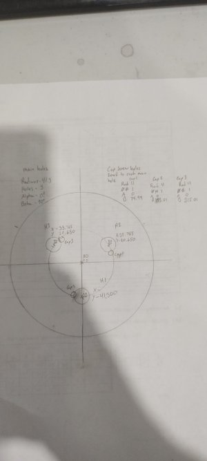
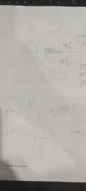
So I'm planning trying to build my own D1-4 back plate for a 4 jaw chuck I've had laying around for ever. So I decided to fool around with layout with DRO whole I wait for my collets to show up. My DRO is only 2 axis but it does have a bolt hole circle function which is great makes making the 3 cam lock pins holes much easier but I'm not sure how how to lay out the retainer cap screws using the DRO with out manually zeroing each hole and using the bolt hole circle function to index each cap screws hole was hoping to lay out everything from central point to help with any errors. Probly not needed but would like to learn how to maintain accuracy and consistency. (I don't own rotary table yet so indexing with DRO is currently best method for me atm)
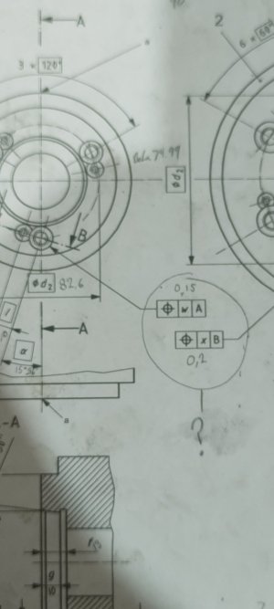
I also don't understand fully what the blueprint detail I've circled in attach picture is referencing. From what I found on symbol syllabus that bullseye means position but not sure what position that really means in conjunction to the information it's provided.
I've attached the prints I will be working off to make it easier to follow along with my question and possible more questions if I run across something along the way. I would appreciate some advice and look forward to learning more.