• Scam Alert. Members are reminded to NOT send money to buy anything. Don't buy things remote and have it shipped - go get it yourself, pay in person, and take your equipment with you. Scammers have burned people on this forum. Urgency, secrecy, excuses, selling for friend, newish members, FUD, are RED FLAGS. A video conference call is not adequate assurance. Face to face interactions are required. Please report suspicions to the forum admins. Stay Safe - anyone can get scammed.

tubing profiles

PeterT

Ultra Member
Premium Member
I'm slowly figuring out weldments in my CAD program. More for fun but also to have that knowledge. I was going to download or internally generate some section profiles which can then be used to rapidly build structural assemblies based on relatively simple 3D line drawings.

Anyways, I noticed that the tubing corner radius is not readily provided on rectangular sections. I can understand that it may well vary, but find it kind of odd its not part of the typical table for a specific supplier or some defined standard. I called Federal Metals to inquire about price & also ask if they sold a certain brand so I could look up a corresponding catalog or mill name, but didn't quite get a definative answer. They said the corner varies by supplier even on same nominal size
https://www.cad-steel.com/steel-sections/hss-shapes-rectangular-and-square

How do you welders work around this? Is there a spec or parameter I am missing or do you just adjust the fabrication based on what is sold?
Have any of you Fusion guys downloaded structural tubing design libraries libraries like this, or are they internal stored maybe?

Sidenote, one can access all the profiles, bracketry & fittings for 80/20. But you have to rob a bank to buy the stuff! lol
https://8020.net/tools-cad
 

Attachments

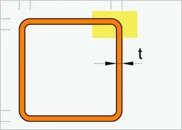
  • SNAG-9-25-2020 0000.webp
    SNAG-9-25-2020 0000.webp
    3.2 KB · Views: 1
Pitch Circle? not quite sure I follow Tom. I suspect the radius is related to wall thickness like when sheet metal is bent. Thicker wall = larger radius? But I think this kind of tubing is ran through a die hot & welded along a seam? so not really sure. My lathe stand is 2x2 & maybe 1/16" radius? OTOH I have aluminum square section tube & its basically square corner, maybe .020" chamfer. And Ive seen 0.25" wall steel like 2x4 that is maybe 0.5" radius or so.
 

Attachments

  • 2020-09-25_23-39-29.webp
    2020-09-25_23-39-29.webp
    2.1 KB · Views: 1
I'm slowly figuring out weldments in my CAD program. More for fun but also to have that knowledge. I was going to download or internally generate some section profiles which can then be used to rapidly build structural assemblies based on relatively simple 3D line drawings.

Anyways, I noticed that the tubing corner radius is not readily provided on rectangular sections. I can understand that it may well vary, but find it kind of odd its not part of the typical table for a specific supplier or some defined standard. I called Federal Metals to inquire about price & also ask if they sold a certain brand so I could look up a corresponding catalog or mill name, but didn't quite get a definative answer. They said the corner varies by supplier even on same nominal size
https://www.cad-steel.com/steel-sections/hss-shapes-rectangular-and-square

How do you welders work around this? Is there a spec or parameter I am missing or do you just adjust the fabrication based on what is sold?
Have any of you Fusion guys downloaded structural tubing design libraries libraries like this, or are they internal stored maybe?

Sidenote, one can access all the profiles, bracketry & fittings for 80/20. But you have to rob a bank to buy the stuff! lol
https://8020.net/tools-cad
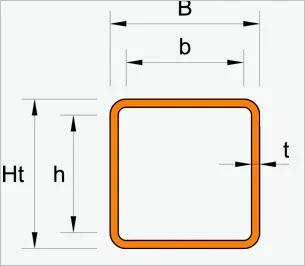
I learned years ago not to rely on any structural specs in the fabrication world. The hard lesson was when I CNC plasma cut over 100 brackets for a project the tubing was to pass through. It felt like every piece of tubing was different. When I called the supplier they laughed at me and said it was like a 2x4—consider it to be nominal. I even scanned in the profile only to discover when the size was right, the radius would change. Also, thickness can wander in tubing far more than flat bar or rod—just to further infuriate machinists.

The learning for me was in the fabrication world you have to design for imperfection. Part of the skill is anticipating allowances into your design. Any time I see someone using a calliper instead of a tape measure to fabricate I know there's a heartache in their future.

Having accepted that, I kind of like designing this way now. It's in line with why I (largely) stay away from machining. I don't have the patience for mm and thousandths of an inch, and have grown to accept imperfection as a fabricator.

Don't get me started on why different types of metal of the same gauge are different thicknesses. I always think about that when using a shrinker/stretcher, or when punching holes on the ironworker...which is also impacted by whether the sheet is hot or cold rolled. It's enough to drive you nuts if you expect precision results. Hence the "design for imperfection" motto.

My 2 cents worth....
 
That's actually useful feedback PT. Because then I can basically make a design table spreadsheet & use some 'eyeball' rule of thumb like Radius = 2 * WT & just call it close enough. More of the CAD power is just having the sections available in a library & plopping it into the model, building up the assembly so to speak. Similarly I have a library of common fasteners & can mate them into holes. I'm a faster modeler than I am a machinist, so finding mistakes on the screen is less painful than in the shop. Even so, mistakes happen.
 
Also, dumb question, but is it reasonable to assume most all these steel tubing profiles have some weld fillet on the inside of one face?
 
That's actually useful feedback PT. Because then I can basically make a design table spreadsheet & use some 'eyeball' rule of thumb like Radius = 2 * WT & just call it close enough. More of the CAD power is just having the sections available in a library & plopping it into the model, building up the assembly so to speak. Similarly I have a library of common fasteners & can mate them into holes. I'm a faster modeler than I am a machinist, so finding mistakes on the screen is less painful than in the shop. Even so, mistakes happen.
Yup, that's what I did years ago when I had a CNC. Or I'd import the profile, but always with the understanding that it's only approximate and I still had to think out the design so when it would get welded up, there would be allowance for variation of material. Not too bad once you train yourself to think that way :)
 
Last edited:
Also, dumb question, but is it reasonable to assume most all these steel tubing profiles have some weld fillet on the inside of one face?
Unless it's seamless, yes.

And you don't need a spec sheet to know it's seamless...you'll know because of the second mortgage on your house to pay for it.
 
Back
Top