• Scam Alert. Members are reminded to NOT send money to buy anything. Don't buy things remote and have it shipped - go get it yourself, pay in person, and take your equipment with you. Scammers have burned people on this forum. Urgency, secrecy, excuses, selling for friend, newish members, FUD, are RED FLAGS. A video conference call is not adequate assurance. Face to face interactions are required. Please report suspicions to the forum admins. Stay Safe - anyone can get scammed.

T Bolts

Matt_b_m

Member
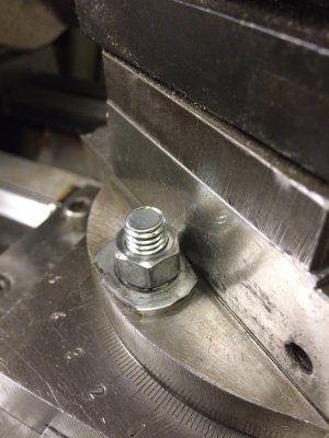
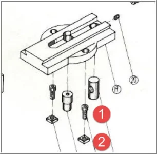
Just took a few moments over lunch to begin to dissemble and clean the new to me Tida-4A lathe i picked up yesterday. Taking my time I removed the tailstock, set it aside and started wiping down the rest. I took a moment to remove the tool post and noticed that the bolts in the compound looked shall I say "too shiny" and out of place. A closer look and it is obvious these along with their washers were added at some point in its life and appear to be hand carved (file, grinder) with matching washers with flat sides as well. I've found the parts diagram for the lathe online, but it doesn't reveal anything more than there is in fact two bolts in this location.
I know finding replacement original parts is essentially a unicorn hunt, but I'm wondering if any of you have had to replace these T bolts and nuts before on any of your equipment, and where you may have found a selection. I am unsure of the original length, but its obviously a part that as long as its long enough, its long enough to work.

As always, any help is appreciated.

Thanks.
 
"the bolts in the compound".... you mean the bolts that clamp the cutting tools in the tool post block? Or maybe bolts that secure the compound at its angle (and they typically engage T-nuts)? Yes a picture with a big red arrow would be helpful :) Anyway, guessing Door#2 - many lathes use regular hex head cap screws. Taiwan lathe, could be metric, probably metric, but could be Imperial, hopefully 'shiny' doesn't mean the previous owner didn't pick the wrong one.
 
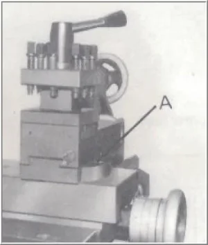
I think he is talking about the compound angle bolts. Something along the lines of this?
ht9.jpg


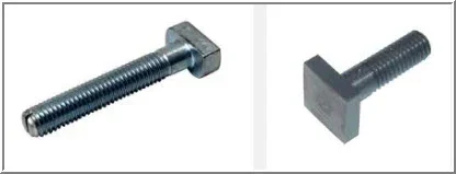
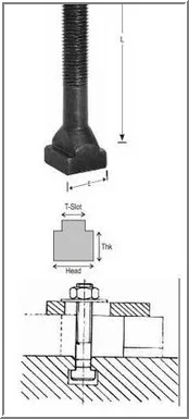
If so, they tend to be a bolt with a T shaped head, which can honestly be made from a grade 8 bolt and cutting the T into them on the head as long as you have enough meat to hold it after.
 
Hi guys sorry to keep you guessing. I should have included a picture. The bolt you have indicated with the arrow is the one I'm referring to. Slightly different on my machine, but same function. I do realize what I have there now will work, and does hold things tight, but my eventual preference would be to replace them. Here is how it looks in my machine.

bolt.JPG
 
Last edited:
Kyle, thanks for the reminder. Never in my life has the thought of "make your own bolts" ever been part of any standard repair thinking before! That sounds like a great project, thanks for the direction.
 
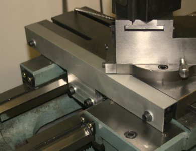
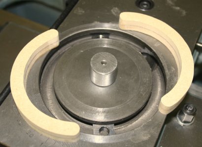
Yup. I thought you were talking about your compound. I'd be interested in what your manual shows. I've seen 2 setups for this on offshore lathes: 1) what you have, T-headed bolts slide in a T-slot head down, threaded part protrudes up through the compound secured by nuts. 2) T-nuts slide in the T-slot & a common hex cap screw screws down into them to secure. That's the case of my lathe. System (2) is kind of a pita in one respect, the nuts can get out of alignment when you remove compound so you have to fiddle around. Its not a biggy & actually I solved this by putting in 2 crescent shaped spacers so they always stay clocked at 180-deg. But the hex bolts are easy to replace I easy to get at with an Allen key. Some solutions
- they do sell T-bolts for milling maching hold-downs, would have to check matching size
- turn up the correct part from round stock (will have to mill flats & thread the end)
- if you can adapt a standard T-nut or make one, you might be able to use that, then fix a threaded rod segment in there for equivalent result. I would ping the underside of threads to prevent threaded stud from turning when tightening.
 

Attachments

  • 12-18-2015 0000.webp
    12-18-2015 0000.webp
    14.1 KB · Views: 8
  • 12-18-2015 0001.webp
    12-18-2015 0001.webp
    9.7 KB · Views: 8
  • 12-18-2015 0002.webp
    12-18-2015 0002.webp
    4.5 KB · Views: 8
  • 12-18-2015 0003.webp
    12-18-2015 0003.webp
    7.6 KB · Views: 8
You have to be extremely careful with T-nuts. I didn't know this until recently and luckily didnt learn the hard way, there is a reason T-nuts wont let you thread a stud all the way through, its to stop you accidentally bottoming out in the channel and blowing out the t-slot. Don't do that.. Personally I would just go with the t headed nut, whatever way you have to do it. Either make a whole new one, or take a grade 8 bolt and machine the head down to fit your t-slot and maybe harden it with a torch and some used oil. Its a pain in the ass to fit them when you will probably have to take the compound off to check it (and you might miss the first swing or two) but in the end clamping on steel isn't going to break anything, accidentally having the wrong length bolt might just destroy that track.

At the same time, turning bolts without destroying threads is a bit of a pain, one of the better set ups I have seen in the past was a coupling nut slit to act as a collet. Or, you can find a chunk of scrap, drill a hole in the center and tap it, then run your bolt in.

Oh, and in case you don't know, the point of the washers is so that the compound doesn't move when you start to tighten it down. Normally double stacked washers are used but a single does the job as well..
 
Peter, thanks for insight into how your machine is set up. The pictures are helpful. Here is a link to the manual and the parts list for my machine.

http://www.g3ynh.info/workshop/tida_td5.html

From what I can tell at this point, what is there is working and does hold without any movement. This I figure should be enough for now and I'll look at making a set of bolts later.... I see that I now must have a mill to make those square cuts.... haha.

Kyle, thanks for the heads up on blowing out the t slots. I like the idea of threading a piece of round stock to hold the bolt. Good tip!

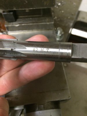
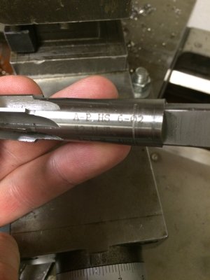
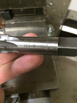
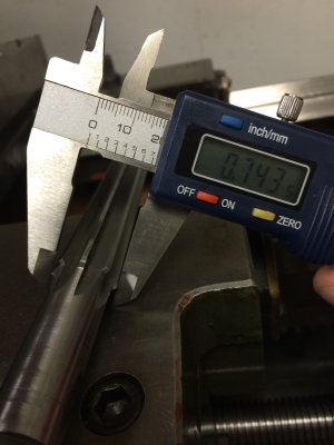
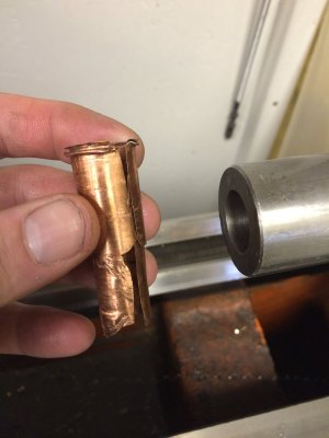
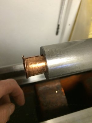
On a side note I just had a moment to retrieve a thin copper sleeve that was in the taper of the tailstock. Removing so would also indicate its purpose... appears that there is some wear, as the live center and the chucks don't hold. Caliper indicates I've got the necessary .7000 for the large end of the taper, it just appears to be deeper than it should be. Any reason why i can't/shouldn't face the end of this down to get the .7000 back? I also found in the box of goodies that came with the machine a #2 MT reamer. I believe someone may have used it and run it too deep.
 
What do you mean exactly with the tape being .7 too deep? Can you take a picture?

As for the needing a mill, you shouldn't in this case really. You can clamp your bolts in the toolholder and then put an endmill in the chuck. If you really want to be creative you could figure out a way to get a vice mounted with a vertical adjustment but milling in a lathe is as old as lathes are.. check out

I'm not saying its the easiest thing to do but it works. If that doesnt work for you, use a file and make the T-head.
 
Well it appears that the .7000 that I need for the large diameter of the #2 taper is deeper in the assembly than the mating tool is, so the two never mate up before the back of the live center or drill chuck touches.

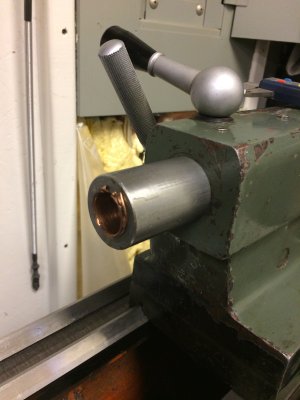
Here is a picture of the copper shim...
copper shim.JPG

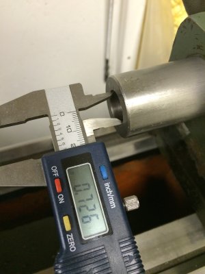
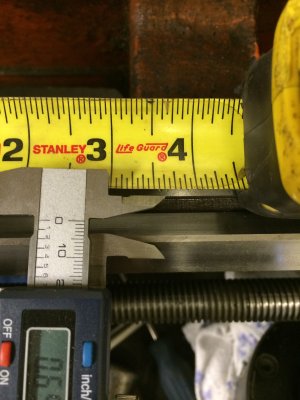
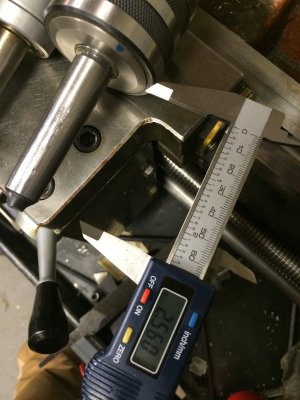
Here is the measurement at the outside edge of the taper
measurement at the opening.JPG

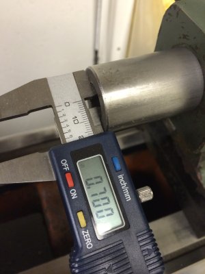
Here is the measurement further in. Which from what I have found is the correct large diameter for the taper to work.
deeper measurement.JPG

The idea was to trim this back to at least this depth and possibly further to get the taper back.
depth.JPG

Thanks for sharing the video, these will certainly come in handy.
vices.jpg
 
Last edited:
What Kyle said about the T-nuts is exactly correct. I've heard of guys cracking cast iron tables if the bolts are allowed to pass through. That's why I mentioned "I would ping the underside of threads to prevent threaded stud from turning when tightening" if you made your own. If you look on the underside of typical commercial mill table T-nuts, they have a couple dents around the bottom 2 threads like they were hit with a chisel 'Ping'! :) These prevent the stud from screwing further & then turning the nut should only be putting tension on the stud...well... at least that's the idea. In the case of the lathe compound with through-bolts into T-nuts, you hopefully would not have this issue providing the bolts are pre-measured correctly so as not to bottom out, but its still a good safety measure.

I looked at the link pic & seems like topside nuts are what they intended.

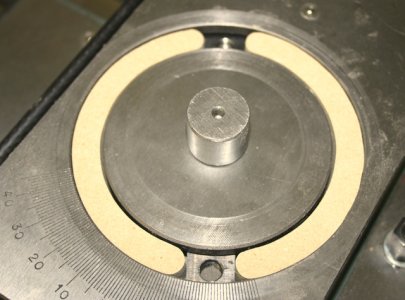
FYI, this is my lathe with cap screws & T-nuts & my wooden C-shape mockups to keep them aligned. Now that I think about it, I never did make metal ones. The woodies are still in 'extended test mode' ha-ha. You can also see a hole off to one side. that where the T-nuts get inserted in from underneath during assembly & slide into position (another PITA imo).

J599x463-03473.jpg
 

Attachments

  • J640x469-04365.jpg
    J640x469-04365.jpg
    48.2 KB · Views: 3
  • J640x475-01481.jpg
    J640x475-01481.jpg
    51.2 KB · Views: 3
Thanks Peter, now I understand exactly what you mean. That's a great idea, I can see how that would get annoying trying to chase the nut around the slot. I did notice the bolts in mine started as carriage head and they do fit in the grove perfectly, but I think that definitely invites the opportunity to over tighten and pull the carriage into the grove causing it to break.
For now, they'll have to hold while I figure out how to get my taper back in shape to hold anything. This is turning into a great project! I got a lathe and a project all in one!
 
@Matt_b_m this will be an awesome project for you for sure! In a permanent application like this, I'd put the all-thread into the t-nut to depth and then weld or braze it in. It's a permanent application so may as well make it a permanent fix.

As for the tail-stock ram, I don't know about facing it off, but whether you can or not 5/8's would be a LOT to face off, and leave you with a shorter, less useful ram. Since you have a reamer for it, maybe you could braze some extra material into the taper and then ream it to the correct size? It would be softer material inside which isn't ideal, but it might work? Not sure.
 
@EricB. Yeah that's a lot of cutting and unfortunately I would lose the length. Its something I'm going to ponder for now, while I pick away at cleaning the rest of the lathe. Before I make any steps in that direction I'm definitely going to look into getting some better measuring tools. Don't get me wrong, my Canadian Tire digital caliper has served me well along with my Stanley tape measure, however I think i can do a bit better on accuracy....
 
Not that I think its the best plan, but it might be worthwhile to look at reaming it out to MT3. Its a whole lot bigger than MT2, but repairing the damage done might not be too easy. The other option could be to make a new ram, although you want to be pretty damn close on your tolerances I would think for that..

Many, many years ago I bought a set of Mitutyo absolute digimatic calipers. I can honestly say they are likely the best purchase in my measuring arsenal I have ever made, and I would STRONGLY recommend them to anyone. They aren't cheap, but nothing worthwhile is. Now I own 3 of them, 1 x 6" and 2 x 8". Dont leave home without them!
 
Here is a post on a repair. I'm sure this is a common issue with older or otherwise damaged lathes, but the solutions are pretty varied.
http://www.homemodelenginemachinist.com/showthread.php?t=5611

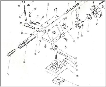
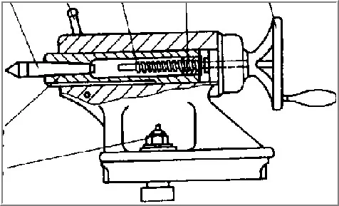
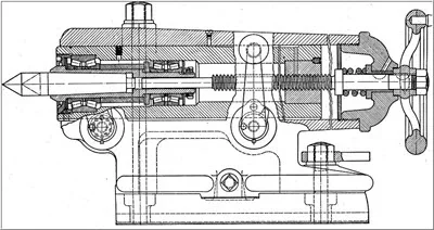
I guess it depends to what degree the quill is damaged & the details of your internals. My gut preference would be try & maintain the MT taper & try & clean up the bore 'just enough' couple thou? I know that MT reamers are available but the question is whether the quill is factory hardened & ground... reaming would probably not go well. The internal dimensions & screw mechanism are other considerations. Will a reamer bottom out on screw nut or mess up whatever holds MT tooling flats on the end? Attaching some typical assembly pics, you can see they vary. I'd want to know more details first before attacking the problem.

Once upon a time I considered buying a new replacement tailstock. I really like the mods this guy did with the capstan (~ minute 23) but was too chicken to mess mine up. Depending on how you feel about inter-breeding your historic machine with offshore stuff, I wonder if buying a complete offshore tailstock assembly would be worth considering? Ie. if the only 'job' were to mill the casting base flat to correct headstock spindle height & mated to your existing base?
12-20-2015 0001.jpg 12-20-2015 0002.webp 12-20-2015 0003.webp
 
@kylemp - I was actually pondering the idea of going to an MT3 as well, and its something I'll consider. For the moment I'll bring myself up to speed on the rest of the aspects of the machine while the repair ideas simmer. Making a new one I think I'd have to consult someone with a proven true tail stock. That being said, last night (aka very early this morning) I had a chance to make some chips after I completed cleaning and oiling. I managed to turn a point in a piece of round stock, and for fun I brought the point of the live center to meet it to see if the two aligned. I was quite surprised to see they were dead on, by the eye at least, as I don't have a dial indicator yet to measure variances that small. That at least was a good feeling. I have to say it was a great night, and the lathe overall is working good. I need to shim the bench a bit, but no big deal I can get that to happen later.


@PeterT - Peter, thanks for passing along the video. I'm quite impressed at the lengths this guy went to to improve function and accuracy. The VFD is a nice touch! He obviously had no shyness about modifying the tailstock! The rack and pinion idea is pretty slick.
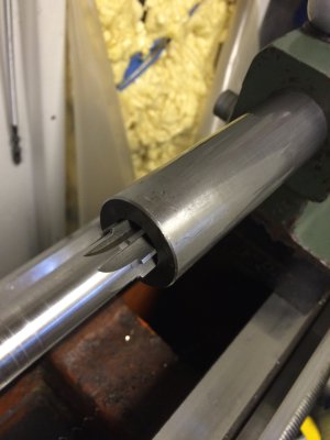
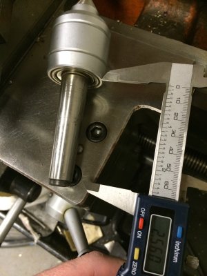
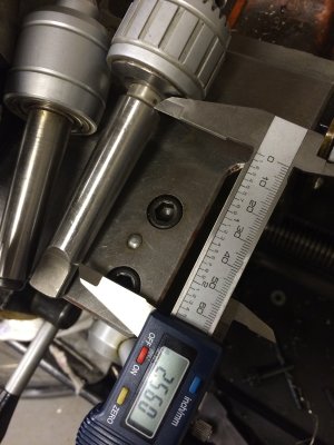
As for the problem with my quill, it appears from what I can tell at this point the taper is intact, but at some point the taper reamer was run too deep. I've included some pictures that might help show how this looks. My measurement shows the widest point of the taper as being over the .7000 mark, which isn't wrong, its just that my taper lengths in the live center and chucks are shorter. Hmmm I wonder if simply getting/making longer taper attachments is the solution...That being said, I've basically ended up with the .7000 large diameter located 5/8" of an inch too deep. Like Eric mentioned earlier, this is really a lot of length to sacrifice..... for now... while I ponder options...
As for any inter-breading my machine, I am not too worried about its history. I don't think it holds a place as being a historic tool with any rarity, and my eventual goal for this machine is to fix the oddities as I go, and making it as accurate as possible within reason.


image2.JPGimage1.JPGimage3.JPGimage4.JPGimage5.JPG
 
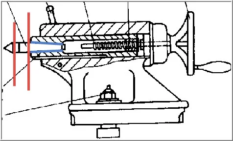
I'm not quite sure I follow. If you are saying a prior reamer attempt was run too deep to the extent the MT shanks are now bottoming out without properly mating the quill ID, then that's a bad omen. Hopefully the sketch markup makes sense. By taking only a smidge off re-dressing the tapered quill bore (but maintaining same taper angle) this translates into proportionately more arbor displacement when landed in mated position. But if its a situation where the shanks now just reside a bit further back in the quill after reaming vs. stock configuration, that shouldn't be an issue. As long as live/dead center point still sticks out far enough & you can spool it & eject it properly etc. no worries. This is outside my pay grade but I'm almost wondering if different arbors have different widest diameter dimensions, even though they are all the same MT-number? You might be chasing your tail on a particular arbor you happen to have, whereas maybe a different live center arbor or drill chuck arbor (of the same MT-number) might be ok? Have you tried other tools already?

Making your own arbors is pretty ambitious. They are typically hardened steel & center ground to a mirror on dedicated machine.
 

Attachments

  • 12-20-2015 0002.webp
    12-20-2015 0002.webp
    17.4 KB · Views: 5
Bad omen it is I'm afraid...The fix that had been in place, that I didn't realize until I got the machine home, was some thin copper around the shank of the taper to take up the difference and allow the taper to meet before the end contacted the quill, pictures included. The sketch makes perfect sense, my blue area is just located deeper :(. I just took a moment to measure my arbors, and it appears when machined they made these to the exact specifications, where as the MT#2 is .7 at the large diameter and .5720 over a distance of 2.560. This alone even when the machine was new from what I can see only allowed a few thou between the arbor and the attached tool (live/dead, or chuck, etc). They definitely didn't follow your sketch and basically I have no distance between the red lines you've indicated. Well I don't think its outside your pay grade, I'm definitely working in a realm above my own at the moment! Haha. The taper by its nature is constant, and is just an angle from center basically. The specs I've listed above are the text book numbers for what I would think (this isn't fact, someone smarter would know...) is the minimum dimensions that this taper can be given to still create enough fit (surface area) to mate the two surfaces and not slip. That being said, the taper overall length could double to 5.120, with the starting end at a point of 0.oo0, and as the taper travels the length of the arbor, at any given point the diameter would be increasing at a constant in relation to the center angle. (Sorry that was long winded, and probably stating the obvious). With that being said, the key to fixing this isn't fixing the quill, as mathematically, its correct from what I can see given how well the MT#2 taper reamer fits the bore. The solution is to find MT#2 arbors that are at minimum 3.185 in length, plus some extra to give me the space between the red lines you've indicated. That to me seems like the better solution then shortening the quill, and might be just as costly as trying to source having one made. It also would then give me additional length to accommodate any wear to the mouth without being so close to the end with no room to spare. This all of course depending upon if such a length is available...

Yeah I figured just by appearance and feel alone I was headed in an ambitious direction on making my own....

Thanks again for the feedback guys, I did just realize this topic strayed off of my original T Bolt question...

taper1.JPG taper2.JPG taper3.JPG taper4.JPG taper5.JPG
 
Back
Top