As some of you know, I have been struggling getting good surface finishes on my small surface grinder. Some of the issues I discovered:
A) spindle axial end play
B) spindle radial play
The above two were causing wheel vibrations and seemed the main source of the bad finishes.
Here is a pic of the blueprint for reference.

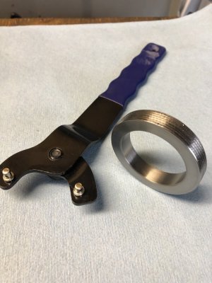
I tackled the end play first. The original design used an internal snap ring to hold the two front angular contact bearings in the housing. There was about 5 thou end play as the outer races of the bearings were not a tight fit in the bore and the whole spindle would move axially.
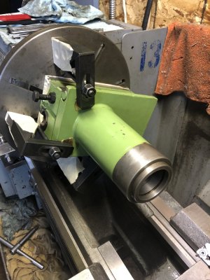
I mounted the whole spindle on the face plate in the lathe and indicated it to run true with the bore. I had previously made a retaining ring. Threads were cut into the spindle to accept the ring.


Now the ring pushes the bearings against their shoulder in the bore and thus the end play is zero.
Next was the spindle radial play. I discovered that the drive side support bearing was very loose in the bore. Roughly 3 thou of play. There was even evidence that the outer race was spinning in the bore. On my grinder the motor was driving the spindle directly via a Lovejoy type coupling. I believe the motor shaft and the spindle were not in perfect alignment either and thus the rear of the spindle was wobbling around, causing the front of the spindle to wobble as well and the wheel to vibrate. On the newer version of this grinder, the spindle is driven via a belt ( see blue print above). So I decided to upgrade mine to that standard. I thought that it would solve a couple of issues:
1) any vibration from the motor would not be transmitted to the spindle; also,
2) the belt would apply a downward force onto the rear bearing thus holding it tight to the bottom of the bore and prevent any wobble. (If that did not work, I would have to find a way to get a better fit between the bearing outer race and the bore...).
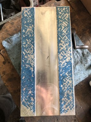
I started by making a new spindle housing back plate. The old one was too short and would not allow the motor plate to be mounted lower down to accommodate the belt drive. I used 5/8” plate for the job as I did not have any cast iron. I scraped the two critical bearing surfaces flat and parallel. Not perfect, but good enough for an amateur.

More images of the two plates


The belt system is a Poly-V J6 profile. Here are the spindle and motor pulleys and one of the reference docs to make them


The motor pulley is necked down to allow for the vertical adjust lead screw to pass by.
All the new components ((plus the old Lovejoy type, straight drive for comparison). Oh, I did make stepped keys since I do not have any metric broaches. I used an available 3/16” one instead of the 5mm and 6mm ones on the spindle and motor shaft.

Here you can see the tight quarters inside the spindle housing. The hole on the bottom is where the lead screw passes through.


After all this, some first results in mild steel... I am very happy so far: vibrations are gone and the grinder is running very smoothly. The old spindle bearings could still need replacement, some day maybe.


A) spindle axial end play
B) spindle radial play
The above two were causing wheel vibrations and seemed the main source of the bad finishes.
Here is a pic of the blueprint for reference.

I tackled the end play first. The original design used an internal snap ring to hold the two front angular contact bearings in the housing. There was about 5 thou end play as the outer races of the bearings were not a tight fit in the bore and the whole spindle would move axially.
I mounted the whole spindle on the face plate in the lathe and indicated it to run true with the bore. I had previously made a retaining ring. Threads were cut into the spindle to accept the ring.


Now the ring pushes the bearings against their shoulder in the bore and thus the end play is zero.
Next was the spindle radial play. I discovered that the drive side support bearing was very loose in the bore. Roughly 3 thou of play. There was even evidence that the outer race was spinning in the bore. On my grinder the motor was driving the spindle directly via a Lovejoy type coupling. I believe the motor shaft and the spindle were not in perfect alignment either and thus the rear of the spindle was wobbling around, causing the front of the spindle to wobble as well and the wheel to vibrate. On the newer version of this grinder, the spindle is driven via a belt ( see blue print above). So I decided to upgrade mine to that standard. I thought that it would solve a couple of issues:
1) any vibration from the motor would not be transmitted to the spindle; also,
2) the belt would apply a downward force onto the rear bearing thus holding it tight to the bottom of the bore and prevent any wobble. (If that did not work, I would have to find a way to get a better fit between the bearing outer race and the bore...).
I started by making a new spindle housing back plate. The old one was too short and would not allow the motor plate to be mounted lower down to accommodate the belt drive. I used 5/8” plate for the job as I did not have any cast iron. I scraped the two critical bearing surfaces flat and parallel. Not perfect, but good enough for an amateur.

More images of the two plates


The belt system is a Poly-V J6 profile. Here are the spindle and motor pulleys and one of the reference docs to make them


The motor pulley is necked down to allow for the vertical adjust lead screw to pass by.
All the new components ((plus the old Lovejoy type, straight drive for comparison). Oh, I did make stepped keys since I do not have any metric broaches. I used an available 3/16” one instead of the 5mm and 6mm ones on the spindle and motor shaft.

Here you can see the tight quarters inside the spindle housing. The hole on the bottom is where the lead screw passes through.


After all this, some first results in mild steel... I am very happy so far: vibrations are gone and the grinder is running very smoothly. The old spindle bearings could still need replacement, some day maybe.


Last edited:
