• Scam Alert. Members are reminded to NOT send money to buy anything. Don't buy things remote and have it shipped - go get it yourself, pay in person, and take your equipment with you. Scammers have burned people on this forum. Urgency, secrecy, excuses, selling for friend, newish members, FUD, are RED FLAGS. A video conference call is not adequate assurance. Face to face interactions are required. Please report suspicions to the forum admins. Stay Safe - anyone can get scammed.

Suggestions on my vfd conversion

DPittman

Ultra Member
I thought I would start a new thread to glean some ideas to help me avoid some mistakes I'm likely to make with out some input from those that know stuff that I don't.

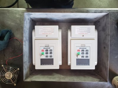
My plan is to mount two recently purchased vfd's in one protective box on the wall and then remotely mount the control panels on the machines themselves.

One vfd will control a milling machine and one will control a drill press. I thought about using one vfd for two machines but the vfds were so cheap I chose to use separate vfds for each machine.

I think I will have a master switch between power source (220v) and the vfd's. I am then undecided whether I need another switch on the machine or if the vfd panel stop/run button is enough for each machine.

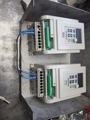
I am wondering if it would be ok to run power line to the first vfd and then just wire the power over to the next one beside it? I won't ever be running the two machines at the same time.

My milling machine already has a forward/reverse switch on it....that gets removed right because the vfd has that built in? 20210416_073332.jpg
 
My milling machine already has a forward/reverse switch on it....that gets removed right because the vfd has that built in?

Not necessarily. You can use this existing switch - wired to the VFDs AUX inputs - as the control for FWD/REV direction. That’s how I run my Bridgeport: use the original switch on the head. Instead of it switching 220V, 3PH, it now switches 5V DC through a telephone multi pair wire.
 
On my mill/VFD, I repurposed the original 220V contactor on/off switch and put it ahead of the VFD (allows the power to be cut to the VFD (no plugging/un-plugging)). It's kind of an emergency stop switch in a way.

Additionally, I use the AUX inputs on the VFD to wire a low voltage emergency stop switch that is mounted on the machine.
 
I'll send you a picture / drawing of my wiring so you can see how I did my 6x26 mill.
Awesome thanks Kevin.
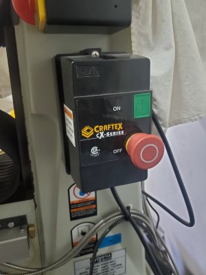
I'm thinking I will use the big old black box switch that is on my mill as the main switch to the vfds ( if I understood you right that is exactly what you did also)
I'm thinking I might just use the vfd panel as the on/off switches for the machines but not sure yet.

One picture of my vfds joined for power source and one of the big black switch I think I will remount to the vfd box as the main switch.20210416_092753.jpg20210416_092738.jpg
 
Something to keep in mind. I believe the instructions for these devices say to never power them off with an external switch while they are running. So wiring up a power switch as an E-stop to the VFD's is not a good idea.
 
Something to keep in mind. I believe the instructions for these devices say to never power them off with an external switch while they are running. So wiring up a power switch as an E-stop to the VFD's is not a good idea.
Oh really? (that's not meant as a cheeky response). I didn't see that in my instructions but I haven't read them or comprehended them fully yet.
Do you mean it's not good to power off the vfd while the motor is running (that's what I hear you say) or it is not good to use an external switch to power off the motor?
 
Do you mean it's not good to power off the vfd while the motor is running (that's what I hear you say) or it is not good to use an external switch to power off the motor?

The VFD has a run button and stop button on it's front control panel. It's not a good idea to kill the input power to the VFD when it's running (powering the motor). I put an ESD switch ahead of the VFD on my mill as a means of powering the VFD off when I'm not using the mill. If push comes to shove and an actual ESD is needed NOW, the switch affords a nice big target to hit. If you leave the VFD powered on all the time the LED display and potentially the fan(s) are on all the time.
 
The VFD has a run button and stop button on it's front control panel. It's not a good idea to kill the input power to the VFD when it's running (powering the motor). I put an ESD switch ahead of the VFD on my mill as a means of powering the VFD off when I'm not using the mill. If push comes to shove and an actual ESD is needed NOW, the switch affords a nice big target to hit. If you leave the VFD powered on all the time the LED display and potentially the fan(s) are on all the time.
Ok good, that's kind of what I understood and was leaning towards also. Thanks.
 
Agree, I never power off vfd with motor engaged. But ultimately use it to cut power vs unplugging


Sent from my iPhone using Tapatalk
 
What I don't get is how these wired signals work. I have wired 5 inputs of which I assume only one can be asserted at a time. FWD-STOP-REV make sense as FWD is exclusive from REV and STOP is simply nothing asserted. How would you wire FWD-STOP-REV and ESD? When you assert ESD more than likely FWD or REV is also asserted. Is there an order precedence where the VFD will obey input 1 over input 2 etc? If there is, it certainly isn't documented for explained anywhere.
 
It is only looking for a voltage (or lack of a voltage) on multiple lines. The can share a common ground , but each positive wire is wired to a separate terminal

Like having 10 telephones and getting a call on one or more than one.


Sent from my iPhone using Tapatalk
 
You could put a contactor before the L1,L2,L3 inputs and have constant voltage to L1c L2C that way the controller is always powered but there is no 3 phase to the controller, You could use another set of contacts on the start switch and use a low voltage dc 3phase contactor so that when you start the motor the contactor supplies the power for the controller and motor.
 
It is only looking for a voltage (or lack of a voltage) on multiple lines. The can share a common ground , but each positive wire is wired to a separate terminal

Like having 10 telephones and getting a call on one or more than one.

Nope.... Don't get it:confused:
 
Nope.... Don't get it:confused:

The controller does the work in the below example input 1 could be start and input 2 be the stop button because they are momentary the controller turns on when you push input one and will run till input 2 is pressed. notice the common line to all switches when you press one it brings the voltage on that pin to 0V telling the controller to start in this example. you could press multiple buttons at the same time and each would do their function.


1618618403932.webp
 
So I press FWD, REV, and STOP at the same time..... what will the controller do?
In that case stop would have top priority if you pressed them at the same time same for start and stop stop would win. parameters come into play as well if parameter (no rev) was set in memory you could press that and it would never switch.
 
In that case stop would have top priority if you pressed them at the same time same for start and stop stop would win. parameters come into play as well if parameter (no rev) was set in memory you could press that and it would never switch.

Nope... still don't get it. In the image you posted if inputs 1-5 are all closed and remain closed which one will be honoured and why?
 
Back
Top