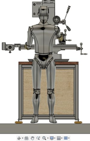
• Scam Alert. Members are reminded to NOT send money to buy anything. Don't buy things remote and have it shipped - go get it yourself, pay in person, and take your equipment with you. Scammers have burned people on this forum. Urgency, secrecy, excuses, selling for friend, newish members, FUD, are RED FLAGS. A video conference call is not adequate assurance. Face to face interactions are required. Please report suspicions to the forum admins. Stay Safe - anyone can get scammed.

Stand Design for benchtop Mill version 2- looking for feedback

StevSmar

(Steven)
Premium Member
Thanks to those who provided comments on my first version of my stand design:
Stand Design for benchtop Mill- looking for feedback
and gently pointed out that my design sucked-LOL.

Version 2 is ready for feedback!

It has:
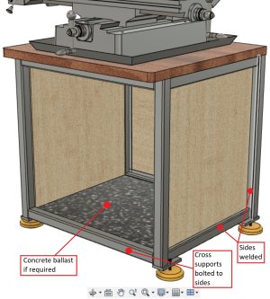
- 2"x2"x1/4" thick square tubing for the sides and hopefully the legs as well (I already purchased this based on the rejected Revision 1 design...)
- The cross members bolt on so the stand can be pulled apart.
- Plywood slides so that full extension slides for the drawers (not shown in below) can be attached.
- Wooden top (already purchased, that I like the look of).
- @LenVW suggested that ballast might be helpful, so it has provisions for including that.
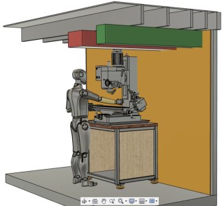
1- overall view.jpg
Based on my experience with my woodworking bench, I think there's enough overhang so I don't hit my feet on the front? See images below.
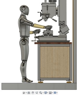
2- overall side view.jpg
3- overall front view.jpg

4- overall view close up.jpg

Below is a detailed view, showing how I'm proposing to put everything together. The model is not finished, it doesn't have things like the bolted joints or parts cut so they don't interfere.
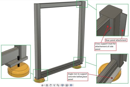
5- Side panel frame.jpg
In above, I added some 1/2" plate for attaching the feet. I'm not too keen on the overhang, but I haven't thought of a better way to allow for adjustment of the feet and not have the feet hit the wall. Hopefully after thinking about it more I'll come up with a better way.
 

Kitchen cabinet toe-kicks are typically 3 1/2" to 4" high, and 3" deep. You will want more clearance when wearing safety boots.

Will you rap your knuckles on the handles with the bench top protruding past the edge of the chip tray? Is there sufficient room behind the mill for all guards to fully open?

I just received these levelling casters that might work for you too; they could be centred under your corner posts. The mount and levelling posts are adequate for my 10x22 lathe, but the nylon wheel does not have bearings and might not be durable for frequent moves.
413n9h-MPFL.jpg


Vevor has a similar product with a different mount.
us%2FJLSPTJFML4PCS60F1V0%2Fsource-img%2Fleveling-casters-m100-9.jpg


g'luck!
 
Not sure if you were planning to make or buy the feet. Most of the ones I've seen have basically a threaded rod with washers & nuts on either side that serve to both jack adjust & secure.
ie. so allow yourself enough room, big rod = big washer. The screw jack from top looks like a good idea, but you probably still want nuts either side of the plate to keep it put.
I'm fond of the rubberized feet myself, they seem to help dampen vibration & conform to floor surfaces.

1668888527910.webp
 
You will want more clearance when wearing safety boots.
Yes, I should allow for more room. I have a tendency to try to squeeze every cubic millimetre out of my workshop and then end up doing something that doesn’t work.
Will you rap your knuckles on the handles with the bench top protruding past the edge of the chip tray?
That’s a great catch, thank-you! Yes, I need to move the front edge back another 20 to 30 mm.
Is there sufficient room behind the mill for all guards to fully open?
It appears everything on my mill is front access:
1668956325477.jpeg

But since I’ve never used a mill before there may be something I’m missing?
I just received these levelling casters that might work for you too; they could be centred under your corner posts.
The mill and stand will be close to 1000lbs, so I’m going to stick with non-caster feet. I do have plans to make up a set of “machine skates” that I can use for the Lathe, Mill and workbench when I need to move them” That’s why the side bottom support is flush with the bottom, so I can use a pry bar to lift up the Mill to insert the skates.

Thanks for the feedback Steve!
 
ie. so allow yourself enough room, big rod = big washer.
Sorry, that’s just me being lazy at this stage of the computer model, there will be a nut underneath to lock the foot.
I'm fond of the rubberized feet myself, they seem to help dampen vibration & conform to floor surfaces.
These are the “vibration dampening” feet I’ve purchased:
1668956815133.webp

They’re the same style I have on my Lathe.

I’m thinking that to get rid of the “overhang” I might make the side bottom crossmember 1-1/2x1-1/2” and bore a hole in it’s top so I can get a socket into access the jackscrew top. I’m not too keen with weakening the crossmember, I guess I can mitigate this by welding some 1/2” metal on the top? Or maybe I can source some 1/4” wall thickness tubing? I’ll mock it up on the model so it makes more sense what I’m talking about…

Thanks for the feedback @PeterT !
 
I checked your earlier thread--I'd forgotten that this mill is 750 pounds! Nonetheless, your design looks plenty sturdy to me.

Re ballast, I don't think that is necessary. Comparing your design to the stand Precision Mathhews supplies, your feet are placed considerably wider. Here is the PM stand:

Stand-top.jpg

And the protruding 'foot rest' looks like a disaster, to me! I don't see why they include it. It doesn't look to me like there is a front-to-back tipping hazard.

The only thing I would add is to give thought to your most commonly used tools. For me, I have a spindle wrench and an 11/16 ratchet that tightens/releases the R8 drawbar. And a brass hammer to tap the top of the drawbar to release the cutter. Plus, of course, the handle for the vise. Do you have handy wall space to keep these within reach or are you thinking to have them in the top drawer of the stand? Next to those pieces, there are a number of other things that you'll also want close by: collet set, keyed/keyless drill chucks, edge finders, centre drills, stubby drill set, countersinks, +++. (Before getting a mill, I didn't appreciate that it is all about tool changes!)

My $0.02 contribution!

Craig
 
Re ballast, I don't think that is necessary.
I suspect that is true, but it’s sure a lot easier to incorporate the ability to add it now than later. It seems like it will be easy to get a few concrete blocks and fit them regardless though.
Comparing your design to the stand Precision Mathhews supplies, your feet are placed considerably wider. Here is the PM stand:
When I saw the PM stand, that spurred my to make my own. I don’t want to make a stand, but it it seemed like it the PM offering was “less than ideal”…

My wife “hates” tools being stored in the open, so I’m hoping to store the tools in the stands drawers, or in cabinets on either side of the mill.
Side cabinets will be something for later though, when I know what I’m doing…

Thanks for the feedback!
 
Yes, I should allow for more room. I have a tendency to try to squeeze every cubic millimetre out of my workshop and then end up doing something that doesn’t work.

That’s a great catch, thank-you! Yes, I need to move the front edge back another 20 to 30 mm.

It appears everything on my mill is front access:
View attachment 28131
But since I’ve never used a mill before there may be something I’m missing?

The mill and stand will be close to 1000lbs, so I’m going to stick with non-caster feet. I do have plans to make up a set of “machine skates” that I can use for the Lathe, Mill and workbench when I need to move them” That’s why the side bottom support is flush with the bottom, so I can use a pry bar to lift up the Mill to insert the skates.

Thanks for the feedback Steve!

I prefer the anti-vibration feet, put the roller style feet give you versatility. Always a plus.
What model of Precision Mathews is that ?
 
Version 2 is ready for feedback!

It has:
- 2"x2"x1/4" thick square tubing for the sides and hopefully the legs as well (I already purchased this based on the rejected Revision 1 design...)

The only thing I see that worries me a bit is structural.

The stand is wider than the mill base by a fair bit. That means there will be a bending load on the front and back Framing. The base of the mill itself is even narrower than the tray which will make it even worse.

Screenshot_20221120-160540_Chrome~2.jpg


I don't know what the cross section of that tubing is, nor do I know the thickness and kind of wood for the top. To be on the safe side, I'd go for a deeper section on those two beams front and back. The beams on the OEM stand look about double the height of what you drew up double the height = 4x the bending strength. Without doing any stress calculations, 4x is prolly a lot safer and better bending strength to shoot for than your drawing shows.

The sides look like they are the same length as the mill base so they are probably ok. But it never hurts to be stronger than needed. On the other hand, if it looks like a hammock hanging between two trees, you won't be happy.
 
The only thing I see that worries me a bit is structural.
I share your apprehension.

The cross member is 2”x2”x1/4” thick square tubing. The hardwood wood top is approximately 38mm thick, plus I’m thinking of putting 2x4’s on the underside which will double the thickness. Or I can double the thickness of the wood top.

My backup plan is:
- Put additional cross member(s), and if that doesn’t work.
- Put bracing in the corner of the top (the drawer will be narrower then) or put another cross support down lower and a center support between them (like a center style kitchen cabinet).
- Put a center support.

Thanks for the feedback!!
 
Last edited:
It doesn't really take much to support 750lbs on such a short span, so long as your not using 16g tube, just about any wall 2" tube will support that, especially once you factor in the top will distribute the weight to all 4 top cross tubes
 
It doesn't really take much to support 750lbs on such a short span
My “guess” from the weight distribution of the mill is that 2/3rd’s of the weight will be at the rear, and 1/3 at the front.

I suspect with 2x2x1/4” thick square tubing and a hardwood top it’s going to be fine. Though I do have backup plans as per the post I put above yours @phaxtris

Thanks for the feedback!!
 
If it's all 2x2x250 you could park a car on top that thing and not see any appreciable deflection, it'll be plenty :)

I would, however, weld the frame together, it will be far stiffer than if you bolt it together, it's going to be heavy, but not so heavy that 2 guys couldn't easily carry it up or down a set of stairs in one piece
 
I would, however, weld the frame together, it will be far stiffer than if you bolt it
I agree with you that it will be far stiffer if it’s welded together. I’m hoping with the wood sides and back it will add stiffness.

My revision 1 design needed to be bolted together to get it out of the basement, but you’re right that this design could be moved fairly easily by two people.
 
The cross member is 2”x2”x1/4” thick square tubing. The hardwood wood top is approximately 38mm thick, plus I’m thinking of putting 2x4’s on the underside which will double the thickness. Or I can double the thickness of the wood top.

My backup plan is:
- Put additional cross member(s), and if that doesn’t work.
- Put bracing in the corner of the top (the drawer will be narrower then) or put another cross support down lower and a center support between them (like a center style kitchen cabinet).
- Put a center support.

2x2x1/4 should be just fine. I didn't realize the framing was that big. Your backup plans are good too but I doubt you will need them.
 
You may want to add a few angle braces from the lower corners to the upper corners on the sides and back of the support frame. These will maintain the rigidity of the square frame.
Don’t go too light on the base frame. It is supporting your investment and the cost of HSS, Angle and some additional welds is a small part of the cost.
 
Don’t go too light on the base frame. It is supporting your investment and the cost of HSS, Angle and some additional welds is a small part of the cost.
I’m hoping… that the rear panel will largely stop any twisting. Since I’m now going to weld it together (I remembered to check the widths of the door from the garage…), that should make it nice and rigid (fingers crossed).

If it has troubles, then I’ll put another cross brace at the front and some side braces (essentially making that drawer narrower due to the braces).

I think it’s almost time to start cutting steel! I’m hoping I can put the frame together over Christmas.

Thanks for the feedback @LenVW
 
Back
Top