• Scam Alert. Members are reminded to NOT send money to buy anything. Don't buy things remote and have it shipped - go get it yourself, pay in person, and take your equipment with you. Scammers have burned people on this forum. Urgency, secrecy, excuses, selling for friend, newish members, FUD, are RED FLAGS. A video conference call is not adequate assurance. Face to face interactions are required. Please report suspicions to the forum admins. Stay Safe - anyone can get scammed.

Speed handle for my milling machine vise

John Conroy

member
Premium Member
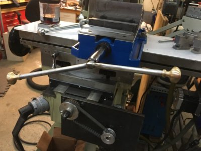
I used a cheap Mastercraft 3/4" socket, some 7/16" CRS and two 3/4" steel balls to make this speed handle for my Kurt vise. I drilled and tapped 3/8" holes in the balls and threaded both ends of the rod. I prefer just 2 arms on the handle instead of three like you see on most of them. It was nice to get out into the shop for a couple of hours for this.

Cheers

 
Hey John did the mill come with that nice chip cover corrugated material? Where can one buy that stuff and what is it called?

Did you need to anneal the socket first before drilling or just drill away? I want one of these handles too but I was going to weld on the handles. You knurled the middle is that to enlarge the diameter and make the handle stick in the middle?
 
I got the way cover on eBay from this vendor.

https://www.ebay.ca/itm/Green-Accor...948673?hash=item35df058941:g:3RYAAOSw1cNaRPfA

I didn't anneal the socket. I wanted to maintain the hardness so the handle won't come loose over time.I drilled through it with a 3/16" then a 7/16" carbide end mill instead of drill bits and it was pretty easy. The knurl increased the OD of the handle enough that it is a very snug press fit into the socket. I used the hydraulic press at work to install it. I used this particular socket because the 3/4" hex on the inside runs the entire length of the socket so it slides all the way onto the vise screw and it's very secure and wont fall off.
 
Nice. What about the balls. Where do you get ones than can be machined or did you anneal loose bearing balls?
 
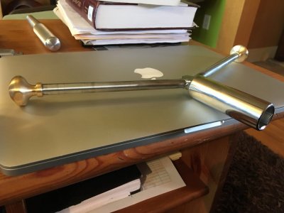
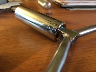
@John Conroy I got inspired by your post to make a two handle speed grip. I didn’t have any carbide end mills to make holes in the socket so I decided to make a square part to insert into the 1/2” hex driver end. I then tig welded handles to that. The square drive part is held in by a screw and washer from the other side. The brass handles are nickel cupboard door knobs which I discovered are just plated and are brass underneath. I threaded the rods #10 to match and tightened them on. I need to paint or plate the rods. Fun little project.
 

Attachments

  • 1F8D0D7D-FD5C-4377-827C-C9E5B8FB8867.jpeg
    1F8D0D7D-FD5C-4377-827C-C9E5B8FB8867.jpeg
    103.3 KB · Views: 24
  • image.jpg
    image.jpg
    82.7 KB · Views: 22
  • image.jpg
    image.jpg
    78.6 KB · Views: 21
Speed handle part II

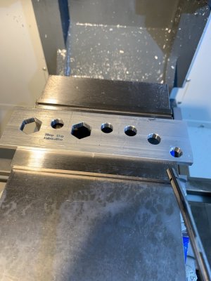
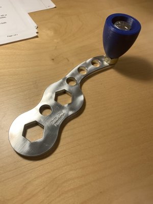
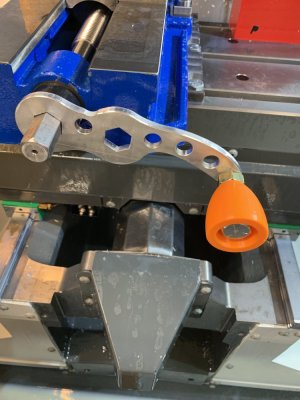
My plastic speed handle keeps breaking so I've made a new one out of aluminium.

1605843364106.webp
 
Cant wait to see it.
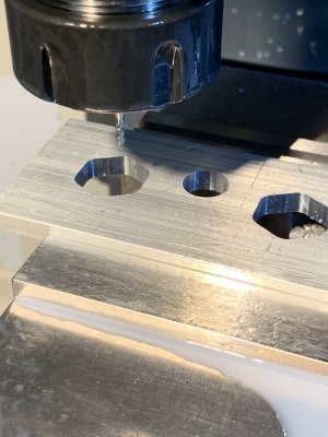
Will you have an operation to cut into the corners of the internal hex's or is the nut sufficiently rounded over that you can mill the hex profile & the resultant EM fillet wont interfere with the nut?
The thicker you make it, the kinder it will be on your hand without a chamfer or roundover along the edge & the longer the hex portion will last.
 
The hex corner is cut with a 2mm EM. The hex hole a few thou over 0.75”
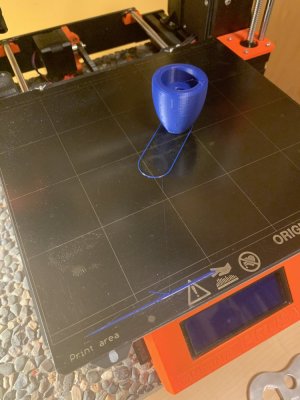
printed a handle handle ;) with blue PETG. I’ve got a 2” 1/2-12 bolt threaded into the last hole and the handle handle spins on that. Two hex holes one for speed and one for leverage.
 

Attachments

  • 6848FAE8-A453-41C0-9B5F-13536CF7E187.jpeg
    6848FAE8-A453-41C0-9B5F-13536CF7E187.jpeg
    109.3 KB · Views: 11
  • BC3D0113-3D6D-4316-8387-132CAD41FF3F.jpeg
    BC3D0113-3D6D-4316-8387-132CAD41FF3F.jpeg
    122.2 KB · Views: 11
  • 2D388891-D1FB-4F97-9FFB-39D12EA2EA59.jpeg
    2D388891-D1FB-4F97-9FFB-39D12EA2EA59.jpeg
    111.7 KB · Views: 10
  • D59EB09F-145E-45B4-96D1-B8E26E4FBD8F.jpeg
    D59EB09F-145E-45B4-96D1-B8E26E4FBD8F.jpeg
    108.5 KB · Views: 11
  • 6315D95F-BF63-497C-A72D-675F2F9221E4.jpeg
    6315D95F-BF63-497C-A72D-675F2F9221E4.jpeg
    121.9 KB · Views: 10
  • AFC64376-17A6-4804-A71D-05828F810227.jpeg
    AFC64376-17A6-4804-A71D-05828F810227.jpeg
    121.4 KB · Views: 10
  • 0F3307BB-56EB-46DF-8580-5B235F21D339.jpeg
    0F3307BB-56EB-46DF-8580-5B235F21D339.jpeg
    108.6 KB · Views: 10
  • 988147FF-5F50-4000-A1C6-871E9871DADA.jpeg
    988147FF-5F50-4000-A1C6-871E9871DADA.jpeg
    87.8 KB · Views: 11
  • 030E1E0D-B053-4E44-A6B8-340C5A2881C5.jpeg
    030E1E0D-B053-4E44-A6B8-340C5A2881C5.jpeg
    91.1 KB · Views: 10
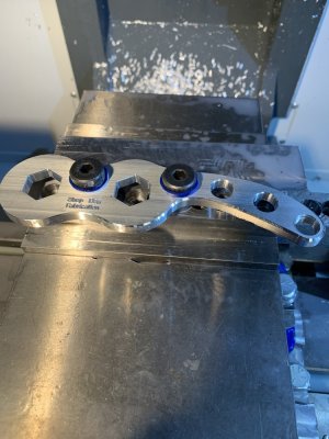
Results!
 

Attachments

  • D1022CFB-9173-4738-A7BE-E74D60937F76.jpeg
    D1022CFB-9173-4738-A7BE-E74D60937F76.jpeg
    131.8 KB · Views: 14
  • C94F9549-8FE7-43B4-8D7D-D9ACF4A31E10.jpeg
    C94F9549-8FE7-43B4-8D7D-D9ACF4A31E10.jpeg
    107.5 KB · Views: 13
Nicely done @Janger!

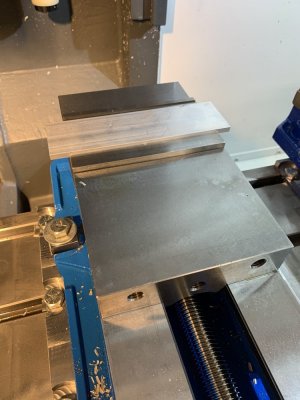
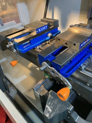
What is the reason for the mounting plates below the vices? To give you better Y-axis location, since the table T-slot does not line up where you like to position the vices?
 
Nicely done @Janger!

What is the reason for the mounting plates below the vices? To give you better Y-axis location, since the table T-slot does not line up where you like to position the vices?

Exactly Rudy. I was also attempting to get the vise bed height exactly the same on the two vises. I didn't quite manage that. They're a few thou different.
 
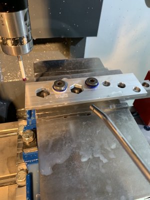
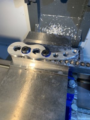
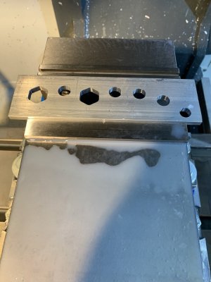
A couple build comments.. Work holding: To hold the handle I used 1/2" shoulder bolts into a hold down bar I made. The handle sits on top of 0.2 thick washers I made that the shoulder bolts go through. The funny plastic washers under the shoulder bolt head are 3d plastic washers. Scratches less. To locate the part in operation 2 and 3 I used the probe on one of the holes to locate the center of the bore. I set up the fusion program to locate part zero at the center of the same hole.

There was some slop in the shoulder bolts I was trying to eliminate. To manage that I dead blow hammered the part from the top side perpendicular to the holes to make sure the part was lined up straight. I noticed the hole center moved about 3-5 thou when I did that hammering. If I didn't do that then the chamfering ops were shifted enough that I got a big chamfer one side and no chamfer on the other. Particularly noticeable when chamfering the back side.
 
Back
Top