• Scam Alert. Members are reminded to NOT send money to buy anything. Don't buy things remote and have it shipped - go get it yourself, pay in person, and take your equipment with you. Scammers have burned people on this forum. Urgency, secrecy, excuses, selling for friend, newish members, FUD, are RED FLAGS. A video conference call is not adequate assurance. Face to face interactions are required. Please report suspicions to the forum admins. Stay Safe - anyone can get scammed.

Solid Toolpost and Rear Toolpost

Ian Moss

Well-Known Member
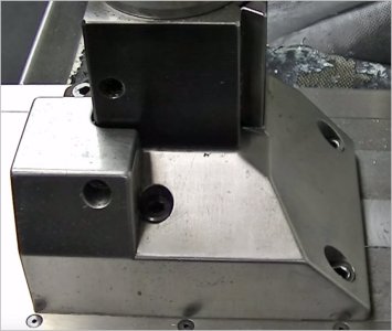
Inspired by the postings of Stephan Gottswinter and Robin Renzetti I made a solid "front" toolpost, rear toolpost and rear compound slide adaption for my 14x60 Mondiale Celtic lathe. I thought it might give others some ideas. I do find that the solid toolposts give a definite advantage with the added rigidity. First pic is the factory setup. The cross slide is secured with the usual two bolts.
IMG_1757.JPG

Compound with toolpost (I have two of these)
IMG_1758.JPG

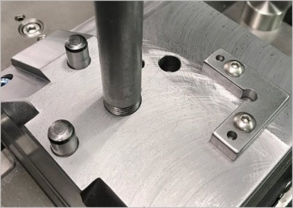
With compound removed. Two small bolts in circular T slot to secure the compound.
IMG_1759.JPG


Six new nuts with spacers to make it easier to align when mounting solid toolpost, and of course to increase rigidity.
IMG_1760.JPG


Solid toolpost riser with two locations for mounting toolpost
IMG_1761.JPG


Front riser with toolpost.
IMG_1762.JPG


Rear toolpost riser.
IMG_1764.JPG


Rear toolpost riser with toolpost.
IMG_1763.JPG

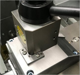
Adapter for mounting compound at the rear. Occasionally there have been times I would have liked to chamfer from the back side of a part. The plate has holes to locate the compound 30 and 45 degrees right and left.
IMG_1765.JPG


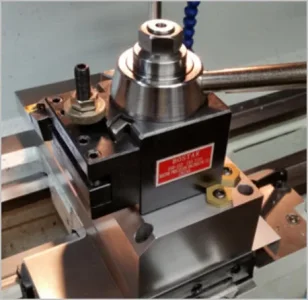
Compound mounted at the rear of the cross slide.
IMG_1766.JPG


If the Covid does not loosen up soon, I may have to do more damage. The toolposts are Rapid original size A, and I am always on the lookout for more holders if anybody comes across any.
 
That’s a very nice design.

I see you surface ground the tops of the blocks. I presume you did the bottom contact surface as well.

What are the sides of the risers made out of? Heavy walled tubing?
 
The risers are solid billet. I machined them on all surfaces first. You may notice the line around the circumference partway down. This was making a bug into a feature. Since turning most of the cylinder and then reversing in the chuck would make it difficult to match the surfaces, I just make the second turning a little smaller to leave a defined edge. I think that looks good. Both ends were surface ground. Recently made a balancer for my grinder stones and it now makes a very nice surface. I found that if I used 5 minute epoxy to add weight to the light side of the wheels (I added to both sides for a better dynamic balance) I could easily approace balance by dremeling off epoxy to reach a balance. The epoxy sticks well to the porosity of the wheel.
 
Now that is a clever solution to endoing parts - especially since the ODs are not that critical.

I had not thought about using epoxy to balance a grinding wheel. Another very good idea.

Any concerns the epoxy may fall off if you use coolant?
 
I like your thinking Ian. I had similar visions for a solid tool post that tied into the circular tee slot reserved for compound vs tapping new holes into cross slide. There is not a lot of room for holes considering the dovetail & call me chicken LOL. And yes, serving double duty to also mount block further aft using the cross slide Tee slots crossed my mind as a consideration, although my existing hole pattern would have to be tweaked to serve double duty. Aside from maybe parting, what other reasons did you want a rear tool post? Directional threading maybe?

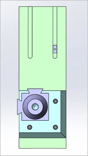
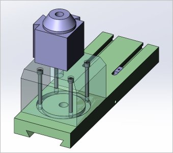
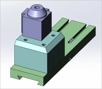
This just shows start of general layout, the tool post locking features still to be applied. One thing I realized about Robs layout is his lathe heights are quite different than mine. The way he retained his tool post laterally with the integrated corner block protrusion doesn't work quite as well with my situation. But I've been collecting other ideas. The dowel pin + corner bracket is one. The mitee-bite cam adjusters (against some kind of pin or slot) is another. The general post-installation consensus seems to be 'much improved' but I wonder how much of that is just mitigating the compound slide & replacing with a much beefier 'foundation'. You noticed a big difference did you? What about surface finish?

Another thing I'm wondering about is lateral position of tool post itself. The way it resides on block at present, cantilever normal cutting forces apply torque to dovetail, lifting against the right side. I haven't thought this through if feasible or practical, but maybe shifting TP to the right would add even more deflection stability?

BTW I'm mulling this solid tool post for accuracy & finish & maybe repeatability, not heavy hogging. I think I'm going to mock it up from a block of wood fencepost. I always learn something at the beta stage that could have been applied to the finished metal part & this is a big block.
 

Attachments

  • SNAG-2022-01-08 4.31.13 PM.jpg
    SNAG-2022-01-08 4.31.13 PM.jpg
    53.8 KB · Views: 15
  • SNAG-2022-01-08 4.23.37 PM.jpg
    SNAG-2022-01-08 4.23.37 PM.jpg
    56.7 KB · Views: 15
  • SNAG-2022-01-08 4.23.28 PM.jpg
    SNAG-2022-01-08 4.23.28 PM.jpg
    46.1 KB · Views: 16
  • SNAG-2022-01-08 4.23.12 PM.webp
    SNAG-2022-01-08 4.23.12 PM.webp
    22.6 KB · Views: 17
  • SNAG-2022-01-08 4.15.28 PM.webp
    SNAG-2022-01-08 4.15.28 PM.webp
    6.8 KB · Views: 16
  • SNAG-2022-01-08 4.12.18 PM.jpg
    SNAG-2022-01-08 4.12.18 PM.jpg
    40.2 KB · Views: 14
  • SNAG-2022-01-08 4.12.03 PM.webp
    SNAG-2022-01-08 4.12.03 PM.webp
    19.8 KB · Views: 16
Last edited:
Mine is turned from a chunk of 3” round aluminum bar. Fits on the existing grooved circular mounting surface that held the original top slide. The eccentric allows me to spin the fixed post to get better tool clearance or throw when needed. Also allows me to drop the Multifix tool holders lower when I’m using a parting tool.

I only used three bolts into the tee slot, but it doesn’t flex so it’s probably enough on my much-smaller lathe.

Helps immensely when parting, way less chatter and digging in.

Turning a 2” offset using a 5” 4-jaw was interesting.
 

Attachments

  • CA882AAE-08DE-49F4-BF25-7A1F56919D21.jpeg
    CA882AAE-08DE-49F4-BF25-7A1F56919D21.jpeg
    555.6 KB · Views: 16
I like your thinking Ian. I had similar visions for a solid tool post that tied into the circular tee slot reserved for compound vs tapping new holes into cross slide. There is not a lot of room for holes considering the dovetail & call me chicken LOL. And yes, serving double duty to also mount block further aft using the cross slide Tee slots crossed my mind as a consideration, although my existing hole pattern would have to be tweaked to serve double duty. Aside from maybe parting, what other reasons did you want a rear tool post? Directional threading maybe?

This just shows start of general layout, the tool post locking features still to be applied. One thing I realized about Robs layout is his lathe heights are quite different than mine. The way he retained his tool post laterally with the integrated corner block protrusion doesn't work quite as well with my situation. But I've been collecting other ideas. The dowel pin + corner bracket is one. The mitee-bite cam adjusters (against some kind of pin or slot) is another. The general post-installation consensus seems to be 'much improved' but I wonder how much of that is just mitigating the compound slide & replacing with a much beefier 'foundation'. You noticed a big difference did you? What about surface finish?

Another thing I'm wondering about is lateral position of tool post itself. The way it resides on block at present, cantilever normal cutting forces apply torque to dovetail, lifting against the right side. I haven't thought this through if feasible or practical, but maybe shifting TP to the right would add even more deflection stability?

BTW I'm mulling this solid tool post for accuracy & finish & maybe repeatability, not heavy hogging. I think I'm going to mock it up from a block of wood fencepost. I always learn something at the beta stage that could have been applied to the finished metal part & this is a big block.

I like it too. I don't have t-slots on my compound, but I bet I could drill and tap it for another base for another BXA tool holder at the back for all sorts of different applications.
 
Helps immensely when parting, way less chatter and digging in

You really should try parting in reverse with an upside down parting tool. The method totally clobbers chatter and will not ever dig in.

It's a perfectly suited method for smaller lathes.
 
@whydontu , did you utilize the circular T slot?

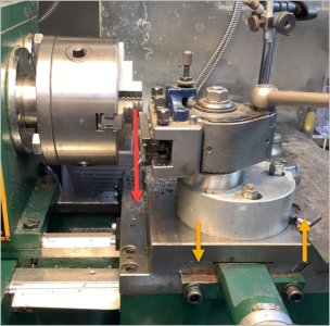
Stealing your pic to scribble on. This is what I was wondering out loud about forces. Any benefit to moving tool post to right? Like I say haven't thought this through. May not play nice for other reasons.
 

Attachments

  • EDT-2022-01-08 5.08.09 PM.jpg
    EDT-2022-01-08 5.08.09 PM.jpg
    100.3 KB · Views: 14
@whydontu , did you utilize the circular T slot?

Stealing your pic to scribble on. This is what I was wondering out loud about forces. Any benefit to moving tool post to right? Like I say haven't thought this through. May not play nice for other reasons.
I‘d have to ask one of our friendly forum engineers, but I can say for sure that all operations are smoother and less chatter.

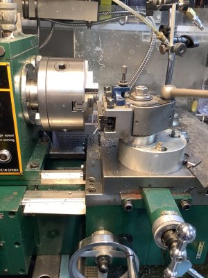
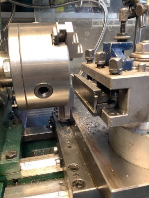
I usually have the slide offset to the left (as in the photo) because it gives me more clearance for chuck jaws. If you look at this photo, imagine the chuck jaws at end of travel open. With the toolpost offset to the left, the chuck jaws can clear the cross slide base and not foul on the upper face of the cross slide.

It’s really not much overhang difference than the original top slide, but removes one set of dovetails from the force vs. flex/movement equations.
 

Attachments

  • 09551058-D0FF-46F9-8B83-955720A01D31.jpeg
    09551058-D0FF-46F9-8B83-955720A01D31.jpeg
    116.4 KB · Views: 11
  • 5C9E2105-D86C-45B8-AA50-4F228DA770C4.jpeg
    5C9E2105-D86C-45B8-AA50-4F228DA770C4.jpeg
    502 KB · Views: 12
You really should try parting in reverse with an upside down parting tool. The method totally clobbers chatter and will not ever dig in.

It's a perfectly suited method for smaller lathes.
I’ve thought about it often, but my cross slide is flat with no slots. It’s pretty thin and I’m worried about getting enough depth of thread to be able to bolt anything to the slide.
 
I’ve thought about it often, but my cross slide is flat with no slots. It’s pretty thin and I’m worried about getting enough depth of thread to be able to bolt anything to the slide.

If your chuck is not threaded on and your lathe will run in reverse,you can just use the parting blade on the front but upside down. That's what I do.
 
Now that is a clever solution to endoing parts - especially since the ODs are not that critical.

I had not thought about using epoxy to balance a grinding wheel. Another very good idea.

Any concerns the epoxy may fall off if you use coolant?
I think the stone is porous enough that the epoxy will not be easily separated, especially if it is a stone meant to carry fluid internally. I mocked up a system 40 years ago that copied a commercial coolant delivery system by having a washer on the face of the porous stone, the washer having a cup shape at the outer edge where the coolant could be pumped in. The inner face had holes and the rotation of the wheel produced a lot of pressure to force the coolant through the stone. I was grinding plastic and it worked very well. Haven't had occasion to do that since.
 
I like your thinking Ian. I had similar visions for a solid tool post that tied into the circular tee slot reserved for compound vs tapping new holes into cross slide. There is not a lot of room for holes considering the dovetail & call me chicken LOL. And yes, serving double duty to also mount block further aft using the cross slide Tee slots crossed my mind as a consideration, although my existing hole pattern would have to be tweaked to serve double duty. Aside from maybe parting, what other reasons did you want a rear tool post? Directional threading maybe?

This just shows start of general layout, the tool post locking features still to be applied. One thing I realized about Robs layout is his lathe heights are quite different than mine. The way he retained his tool post laterally with the integrated corner block protrusion doesn't work quite as well with my situation. But I've been collecting other ideas. The dowel pin + corner bracket is one. The mitee-bite cam adjusters (against some kind of pin or slot) is another. The general post-installation consensus seems to be 'much improved' but I wonder how much of that is just mitigating the compound slide & replacing with a much beefier 'foundation'. You noticed a big difference did you? What about surface finish?

Another thing I'm wondering about is lateral position of tool post itself. The way it resides on block at present, cantilever normal cutting forces apply torque to dovetail, lifting against the right side. I haven't thought this through if feasible or practical, but maybe shifting TP to the right would add even more deflection stability?

BTW I'm mulling this solid tool post for accuracy & finish & maybe repeatability, not heavy hogging. I think I'm going to mock it up from a block of wood fencepost. I always learn something at the beta stage that could have been applied to the finished metal part & this is a big block.
Yup, rear parting tool and threading operations were where I expected to use the rear toolpost. I like the Rapid toolpost because it has such a large footprint. I have never had any problem with the post moving in a cut. I have bushed the inside of the center hole so it is a close fit on the fixing screw, and the tool has a through hole for a locating pin if I wanted to use that, but I like to be able to rotate the tool post. I don't think that there is likely to be any tendency for the cross slide to lift on the rhs of my lathe, the dovetail is pretty wide.
 
Mine is turned from a chunk of 3” round aluminum bar. Fits on the existing grooved circular mounting surface that held the original top slide. The eccentric allows me to spin the fixed post to get better tool clearance or throw when needed. Also allows me to drop the Multifix tool holders lower when I’m using a parting tool.

I only used three bolts into the tee slot, but it doesn’t flex so it’s probably enough on my much-smaller lathe.

Helps immensely when parting, way less chatter and digging in.

Turning a 2” offset using a 5” 4-jaw was interesting.
I have a Aaa multifix on an old Boley split bed lathe. I have always been concerned about the small footprint on the multifix posts, but they have a good following. The toolposts I have present a much bigger footprint on the compound or solid toolpost, and I really like that. I can also drop my holder lower than the mounting surface by using the offset securing bolt location.
 
good excuse to go to the shop and try this out. Have to move all the mill controller parts off the bench.

Well..... How did it work? Or did you chicken out like I did the first time around?

I recall that I was initially afraid of lifting the cross-slide off the bed. But in practice that doesn't happen because the geometry is biased to let go instead of digging in. Digging in is bad even when directionally toward the bed. So all in all it was an awesome experience once the dust cleared.

Given a choice, I'll prolly always try to part properly. However, when the going starts to fall apart - as it often does - I'll flip the tool and cut in reverse in a heart beat! It has always worked!
 
Back
Top