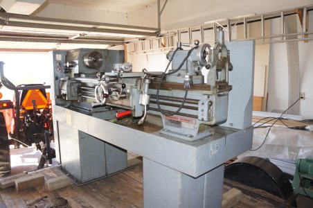
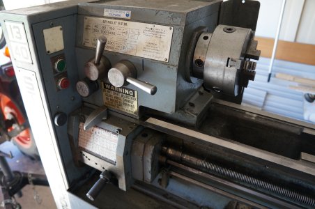
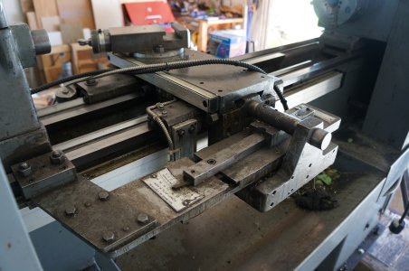
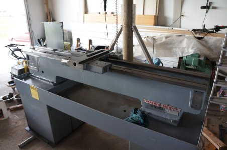
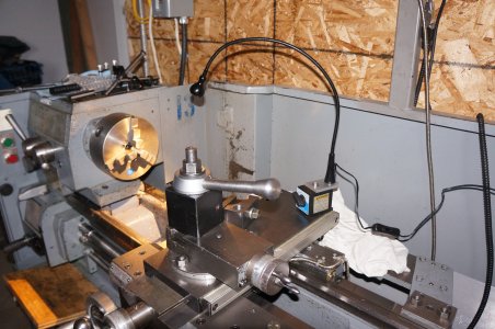
My Standard Modern 13X40 lathe is all metric. I want to be able to cut inch threads as well. It did not come with the change gears. Called SM to see if they are available: YES. Great, how much? $$$$$$$$s! OK thanks, I'll pass for that price. Off I went to make my own. This time I had my mill and universal indexer. So I made a few gears, the most important one being 127T transposing gear because it is the lowest common denominator for the 254mm/1in ratio. I have enough room on my lathe for such a big gear as long as my change gears were all DP24s , 14.5 PA.
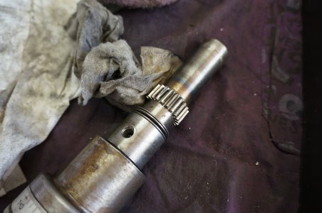
Oh, wait, I have no arbour for my gear cutter; so I made one out of an old lawn mover spindle
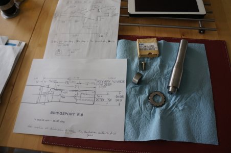
I used mild steel plate, 1/2 thick, and rough cut all the gear blanks with an appropriately sized hole saw and turned to size after. Except for the 127T one, which I rough cut on the band saw into an octagon shape and turned to size on the lathe.
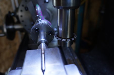
My first gear was the 45T in the set - if I mess up, then he would be the least amount of work to redo.
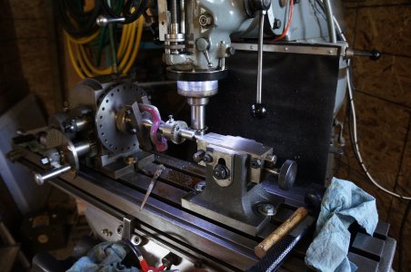
Here is another view
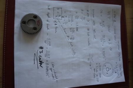
And here is the final product with some of the calculations I did to create it
As Tom Lipton says: "Rinse and Repeat" for the others. The 127T gear is special since 127 is a prime number and there is not way for either "direct" or "indirect" division of the 360* circle. But since I have an Universal Dividing Head with all its change gears, I was able to use the "differential indexing" method to divide the 360* circle into 127 equal parts.
Here is the set-up
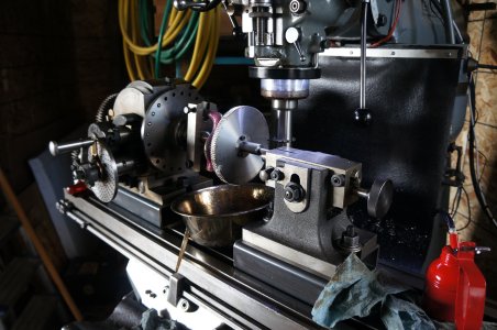
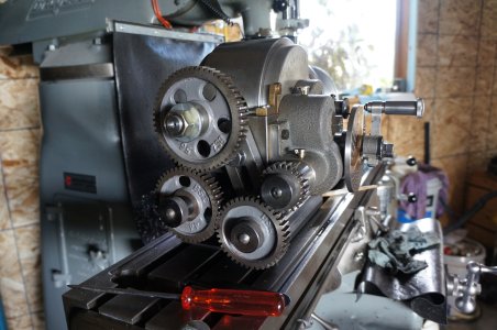
And a view of the dividing head's change gears. In a nutshell here is how "Differential Indexing" works mechanically: the indexing plate is on a shaft which is linked via the change gears to the dividing head's spindle. As you rotate the indexing lever the appropriate # holes along the indexing plate, the dividing head spindle moves. Also - through the gears on the back - the shaft upon which the indexing plate sits moves; therefore the indexing plate moves - hence the term "differential" (that is what's different from "direct' or "indirect" indexing). Kind of hard to describe; easier to grasp when you see it in action and quite a clever thing. Kudos to the engineer that came up with it!
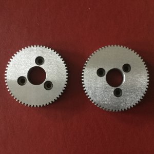
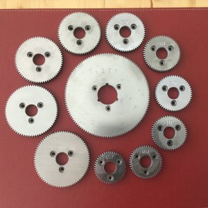
After many hours of cutting, here they are. I ran them on my tool & cutter grinder for a nice surface finish - because I had no surface grinder at the time. All were engraved with the respective # teeth on the pantograph.
A close-up of the surface finish
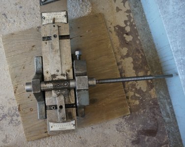
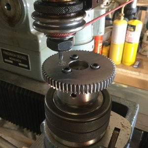
Here is the set-up for the engraving process using the Deckel Pantograph
And all done
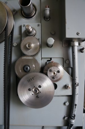
And two in use on the SM1340 (here they were not surface ground or engraved yet).
Oh, wait, I have no arbour for my gear cutter; so I made one out of an old lawn mover spindle

I used mild steel plate, 1/2 thick, and rough cut all the gear blanks with an appropriately sized hole saw and turned to size after. Except for the 127T one, which I rough cut on the band saw into an octagon shape and turned to size on the lathe.
My first gear was the 45T in the set - if I mess up, then he would be the least amount of work to redo.

Here is another view

And here is the final product with some of the calculations I did to create it

As Tom Lipton says: "Rinse and Repeat" for the others. The 127T gear is special since 127 is a prime number and there is not way for either "direct" or "indirect" division of the 360* circle. But since I have an Universal Dividing Head with all its change gears, I was able to use the "differential indexing" method to divide the 360* circle into 127 equal parts.
Here is the set-up

And a view of the dividing head's change gears. In a nutshell here is how "Differential Indexing" works mechanically: the indexing plate is on a shaft which is linked via the change gears to the dividing head's spindle. As you rotate the indexing lever the appropriate # holes along the indexing plate, the dividing head spindle moves. Also - through the gears on the back - the shaft upon which the indexing plate sits moves; therefore the indexing plate moves - hence the term "differential" (that is what's different from "direct' or "indirect" indexing). Kind of hard to describe; easier to grasp when you see it in action and quite a clever thing. Kudos to the engineer that came up with it!

After many hours of cutting, here they are. I ran them on my tool & cutter grinder for a nice surface finish - because I had no surface grinder at the time. All were engraved with the respective # teeth on the pantograph.
A close-up of the surface finish

Here is the set-up for the engraving process using the Deckel Pantograph

And all done

And two in use on the SM1340 (here they were not surface ground or engraved yet).


