• Scam Alert. Members are reminded to NOT send money to buy anything. Don't buy things remote and have it shipped - go get it yourself, pay in person, and take your equipment with you. Scammers have burned people on this forum. Urgency, secrecy, excuses, selling for friend, newish members, FUD, are RED FLAGS. A video conference call is not adequate assurance. Face to face interactions are required. Please report suspicions to the forum admins. Stay Safe - anyone can get scammed.

SM 11" 2000 series help

IonMan

Member
Hi everyone! First post here and i'm excited to get started in the world of machining.

As a note, I'm almost completely green to owning/operating a lathe, but am a quick learner. So forgive some incorrect terminology or flawed explanations.

I recently purchased a Standard Modern 11" 2000 series lathe for my home shop from one of the members here, Darren. Great guy and easy purchase.

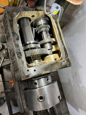
Somehow the feed gear shafts key spring/retainer popped out. I ordered new parts which arrived very fast, Welded a little damage in the smaller gear and reassembled.

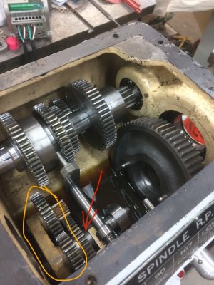
I've never been in a headstock of a lathe, and couldn't find any good pictures of what all is supposed to be on that feed gear shaft but it seems as if the gears are free to slide along it without any sort of spacer to keep alignment in check. I took a picture from one of the posts on this forum and circled the areas i'm referring to.

So on this feed gear shaft, there is a cluster of gears right at the beginning that remain in place (yellow circle), then a small loose gear, washer, larger loose gear, approximately 1" of space, the support, then the set screwed collar.

Is there supposed to be any additional components here (red arrow)? Just seems as though its all quite free to slide. that first cluster seems to have around 1/4" of play. The larger loose gear is free to contact the support when the shaft is pressed inwards. Maybe this is just how it is and is fine since its in an oil bath.

Long story short i would love any information someone can provide to me.

Cheers
 

Attachments

  • 7869_6f545563cba310069d1f45b7a74ce24c (1)-1.jpg
    7869_6f545563cba310069d1f45b7a74ce24c (1)-1.jpg
    138.3 KB · Views: 17
Welcome aboard! I'm sure one of the guys around here will be able to compare theirs to see if you're missing a spacer or something. I know @Brent H has been into a few of them.

The parts manual that we have is lacking in the detail department.
 
Wish I could offer you more than a warm welcome, but sadly that's all I have. There will be some standard modern experts along here shortly.
In the meantime, welcome from Lillooet BC.
 
Been in there many times, but it was so long ago its a blur. The manual doesn't have an exploded view, but does lay the parts out as they are assembled....maybe this will help (attached image)
 

Attachments

Been in there many times, but it was so long ago its a blur. The manual doesn't have an exploded view, but does lay the parts out as they are assembled....maybe this will help (attached image)
Now that i look at that manual page again, it almost looks like #31 is missing. Spacing Collar.
 
Did it drop into the sump when you pulled the shaft?
I swear i checked thoroughly but my lighting isn't the best there currently. Going to take another look tonight. Wouldn't that be nice!

Or if someone gave we dimensions on the spacer i could just turn one without using power feeds.
 
If the spacer is brass or other non ferrous material, you'll need to go fishing. Its probably in there. Otherwise, yes , now that you're a machinist, you can probably make one ;)
 
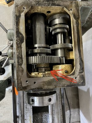
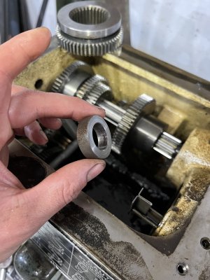
Well would you look at that. I found the bloody little spacer hiding in a far corner under a gear. Feed gear shaft assembled back together beautifully!

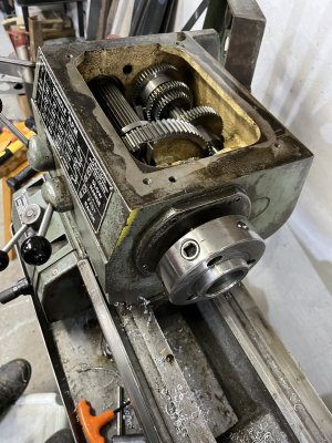
Now I’m having trouble getting the bearing collar to thread back onto the spindle. I was hitting it in with my dead blow and was working well but won’t go any further and threads won’t engage yet. I tried a steel hammer and piece of wood but doesn’t seem to be doing it and I don’t want to hurt anything.

Any tips or tricks?

Also once I do get the threads going… how tight should I make it (preloading the bearing)?


Thx!
 

Attachments

  • BA6F184E-6D1C-4A64-A779-694EB4F2939D.jpeg
    BA6F184E-6D1C-4A64-A779-694EB4F2939D.jpeg
    556.1 KB · Views: 14
  • 49EBBF75-AE25-4E79-8D01-687D08493C93.jpeg
    49EBBF75-AE25-4E79-8D01-687D08493C93.jpeg
    579.7 KB · Views: 14
  • AB6EAD4E-5006-4697-9D08-13F1A9C9E7DA.jpeg
    AB6EAD4E-5006-4697-9D08-13F1A9C9E7DA.jpeg
    403.1 KB · Views: 14
Glad you found it.

Did you take the spindle right out? You generally don't want to be doing that if it can be avoided.

Not sure why the collar won't go on. Might try heating it up a bit . Preload is generally set initially by putting everything in neutral so the spindle is free , and spinning the chuck. One revolution is what you want on a fairy hard spin. Then run the machine at 1000ish rpm for 20 to 30 mins, no load. The bearings should be warm, not too warm, not too cold. 10*C over ambient is probably good.
 
Ensure that the conical bearing cup behind the D1 spindle head is not cocked and free to properly engage the conical bearing. Might take a light tap on the back of the spindle to free things up and then you can tap the spindle up to where you can engage the draw nut. Also be sure there is a brass disc under the set screw of the locking collar nut to prevent mangling the threads.
 
The spindle looks to be not fully seated in the HS. It is hanging up on something. Rear bearing perhaps?

I tend to use a threaded rod to draw the spindle into the HS. This allows you to put pressure on the inner race of the rear bearing (by using a tube over the spindle) to push on it.
 
I won the battle! Thx to everyone for info or suggestions. I ended up heating the bearings to 150f and they installed WAY easier. Lubed it all up, tightened collar to zero bearing play, set preload so that one medium hard throw on the chuck was one full revolution.

New bucket of oil arrives tomorrow then I’ll run it at 1000 rpm for a while and watch bearing temps.

It was pretty fun diving into this machine!
 

Attachments

  • 66D8CA34-42B7-4A30-98D1-4A4B44733612.jpeg
    66D8CA34-42B7-4A30-98D1-4A4B44733612.jpeg
    621.8 KB · Views: 8
Back
Top