• Scam Alert. Members are reminded to NOT send money to buy anything. Don't buy things remote and have it shipped - go get it yourself, pay in person, and take your equipment with you. Scammers have burned people on this forum. Urgency, secrecy, excuses, selling for friend, newish members, FUD, are RED FLAGS. A video conference call is not adequate assurance. Face to face interactions are required. Please report suspicions to the forum admins. Stay Safe - anyone can get scammed.

Shop press build

ShawnR

Ultra Member
Premium Member
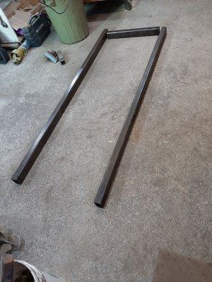
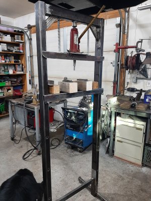
I decided to finally build a shop press. Working on a meat slicer now and I need to remove a pressed bearing. Although I could go somewhere (a puller does not seem to even scare it), I am going to use up some material in the shop and make it into something useful other than a tripping hazard or fall threat! I have often wanted one but would not stop that project to build one. I am hoping to be able to do some press breaking with it too.

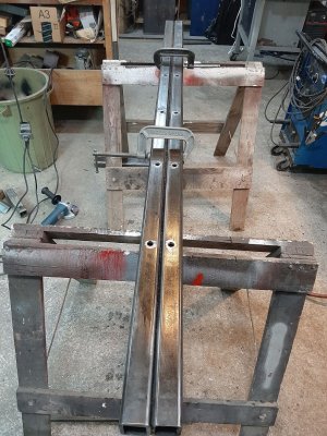
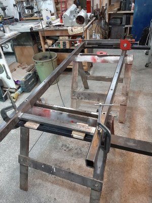
The posts and top are 2 x 3 x .250" tubing. The jack will be a 6 ton for now because I have one to prototype with but hoping (considering based on input here) to move to a pneumatic/hydraulic jack if all goes well when the press is done. Like this one but the 12 ton version (that page is not loading for me ) Is the pneumatic version good for this application or would the lack of "feel" or speed a bad thing for this application?


The holes are 9/16" right now. Question...how do I know or find the shear strength of a bolt/rod? For this application, I am thinking that 9/16" is lots. I was going to go 1" when I started planning but considering the tube is only 2" wide, that would not leave a lot of meat beside the hole.

The holes are 12" apart since the jacks have about 10" of travel, I figured this would be ok.

Input is good. I have not used presses very much.

Thanks
Shawn
 

Attachments

  • 20211102_102107.jpg
    20211102_102107.jpg
    173.3 KB · Views: 7
  • 20211102_125448.jpg
    20211102_125448.jpg
    159.8 KB · Views: 8
  • 20211102_134745.jpg
    20211102_134745.jpg
    172.5 KB · Views: 7
Last edited:
With a pneumatic jack, you build air pressure to move the ram, so if it’s stuck and you keep feeding it air, once it loosens the air pressure should drop. If that makes sense.
 
Question...how do I know or find the shear strength of a bolt/rod?

I use an app called iEngineer. Here is the result (yellow arrows - shear strength depends on how the bolt shoulder / thread is loaded) for a 5/16-12, gr8 bolt.

30396BDA-0532-41CD-97EE-734ECE089CEF.jpeg
 
With a pneumatic jack, you build air pressure to move the ram, so if it’s stuck and you keep feeding it air, once it loosens the air pressure should drop. If that makes sense.

Are you talking about an air cylinder? I think the jack I was referring to just uses an air actuator to move the hydraulic pump.

@RobinHood Thanks. That is the number I was looking for. Even higher than I expected so considering there will be 4 contact points, a Grade 8 9/16 bolt will have much more shear resistance than a little bottle jack will deliver. I will check out more engineering sites. I googled the other day but the first few hits did not yield what I was looking for. Figured someone here could give me quick direction. Thanks!
 
I made my own shop press and then realized that farmers are selling shop presses 10x as strong for 5x less then the price of steel used in them.

Whatever you do do NOT base your design on stuff in Princess Auto / Busy Bee / KMS / Canadian Tire etc. Their designs are marginal even when you increase them by a factor of 1.5. If you are going to copy the design make sure you more then double the strength of everything they have - preferably triple it.

I went with 1.5 and I am not too happy. It is true that the presses they sell deform under load - when you do actual calculations with mild steel you see at full load PA press when positioned perfectly will be at 90% or so of its plastic deformation limit.
 
I've not used one those pneumatic/hydraulic jacks so I guess I could be missing something, but I think a pneumatic press seems like a bad idea. The reason is, what being pressed (out) can or will sudden present about no resistance. Nothing violent happens at that point with a hydraulic press as liquids more or less don't get compressed where a gas does and will want to keep things moving at a high rate of speed once resistance drops/disappears. Good news is it might do double duty as a hammer :D

If I've miss something with how they work, apologies and i look forward to my education :)
 
air over hydraulic is just your hydraulic jack that in addition to a small emergency hand pump (usually supplied) has a small air powered motor that does all the hydraulic work. Instead of you doing all the work the air does it in not too efficient manner. But it is small.

You can have electric hydraulic jack where electric motor does the same thing - electric hydraulic pump systems are common.

If you can get air over hydraulic - do it - it makes working the press much easier. Heck, next step is electric hydraulic - used in bigger presses a lot.
 
@Mcgyver ...what @Tom Kitta says. The air system just does the pumping for you. It is still a hydraulic bottle jack. I figure if the air was controlled by a foot valve, then it frees up the hands to hold or position the work. I thought safer and more convenient. Yes Tom, mildly considering a full electric version.....That would be Gucci!! :D I have not looked for components yet. I will do some research tonight
 

Attachments

  • 20211103_154902.jpg
    20211103_154902.jpg
    430.8 KB · Views: 4
I made my own shop press and then realized that farmers are selling shop presses 10x as strong for 5x less then the price of steel used in them.

Whatever you do do NOT base your design on stuff in Princess Auto / Busy Bee / KMS / Canadian Tire etc. Their designs are marginal even when you increase them by a factor of 1.5. If you are going to copy the design make sure you more then double the strength of everything they have - preferably triple it.

I went with 1.5 and I am not too happy. It is true that the presses they sell deform under load - when you do actual calculations with mild steel you see at full load PA press when positioned perfectly will be at 90% or so of its plastic deformation limit.
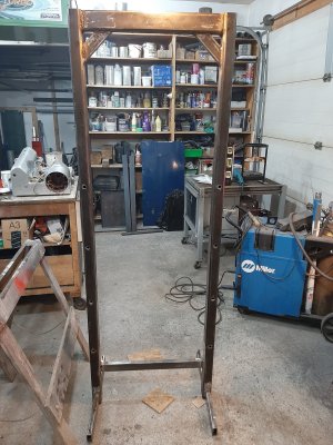
I have looked at some presses for design ideas but there are not many options for a simple press. I am just using what I have and figure the rectangle tube at wall thickness of 0.250" will be strong enough for my work. I know a lot of them use channel but this is another of my projects to get something out of stock in the shop. It seems tall but probably by the time I mount the jack, it might not be too bad. Having the room below it might be handy sometimes. I did not want a bench press.
 
Like this one but the 12 ton version (that page is not loading for me ) Is the pneumatic version good for this application or would the lack of "feel" or speed a bad thing for this application?

I have a 12 ton that I use for changing tires on my big row crop tractor. You are correct about how it works. The air just moves the pump Lever so you don't have to manually pump it. The thing only requires 20psi or so to work, but it needs huge airflow and it really really really slows down (even at 100psi) when the Hydraulic pressure gets high. Frankly, I have never been thrilled with the way it works but it does beat hand pumping.

It has zero feel to it. That's bad when you are working close to the edge. At those capacities, there isn't much feel to begin with.

I put mine in my 20 ton press once when the original jack started leaking, but replaced it with another standard jack not long afterward because I crushed too many parts with it.
 
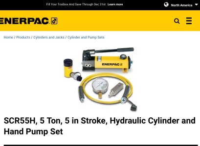
This looks interesting. Might be nicer than a bottle jack. Anyone familiar with it?

I haven’t used the PA version, but we use the real one all the time. The ability to change cylinder dimensions, and remote-mount the pump makes for much easier implementation on our test stands (we do pressure testing of industrial valves, and holding the test heads with a frame and hydraulic jacks is 100x faster than bolting up pipe flanges)


Attachments

  • 5E3D1007-F331-47C1-83B3-088EC2ABAB82.jpeg
    5E3D1007-F331-47C1-83B3-088EC2ABAB82.jpeg
    113.1 KB · Views: 2
This looks interesting. Might be nicer than a bottle jack. Anyone familiar with it?


I have the 10 ton version and my neighbour has the 4 ton version. They work great for the things they were designed to do but prolly would not work well in a hydraulic press.

Around the farm, they are almost indispensable. If mine broke, I'd go get another one the day before. The separate pull cylinder is also quite useful.
 
Pretty much finished I think. I made the shelf out of 1 x 2 x 0.125 tubing. I will see if it stands up without bending. The post has a 0.250 hole in it to act as a pilot hole so I can make different anvils for it (terminology?) The one in there is just a 1/2" piece of dowel with the pilot stub turned on it. I tried to make the press versatile as I have no particular intention for it other than just to have a shop press. I suppose the job at hand will dictate any future additions. Paint is next.... :)

Having said that, I tried pressing a bearing off the Hobart motor shaft and it did not seem to move. I am reluctant to just go hard as I am not sure if it just presses on but that is a point for the hobart thread.

Thanks for the input everyone.
 

Attachments

  • 20211109_095656.jpg
    20211109_095656.jpg
    466.8 KB · Views: 14
Boy, she is beautiful!

At a safety factor of 1.0 (reasonable for something like that in a shop environment where bending out of shape in not a big issue), a 36" span, and plain steel tubing, your tubing will take about 1250 pounds each or 2500 pounds total (evenly distributed) before permanently deforming. That looks like a 6 ton cylinder so best to be very careful. Your top section looks MUCH stronger than the business end. The column load on the posts is mostly tensile so they should be fine. Prolly MUCH stronger than the top or bottom section.

That jumps to 8000 pounds total if you weld another 1x2 above or below (not beside) the existing ones.
 
Last edited:
Boy, she is beautiful!

At a safety factor of 1.0 (reasonable for something like that in a shop environment where bending out of shape in not a big issue), a 36" span, and plain steel tubing, your tubing will take about 1250 pounds each or 2500 pounds total (evenly distributed) before permanently deforming. That looks like a 6 ton cylinder so best to be very careful. Your top section looks MUCH stronger than the business end. The column load on the posts is mostly tensile so they should be fine. Prolly MUCH stronger than the top or bottom section.

That jumps to 8000 pounds total if you weld another 1x2 above or below (not beside) the existing ones.

@Susquatch Thanks! Not many of my projects receive that kind of comment! ;)

Where do you get the information? As mentioned earlier with regards to the shear strength, I am not sure what to even search for when looking for bending data and when I have tried, I probably get confused by what I find. I did intentionally build the top solid. ie paid more attention to my welding...;) as I figure this needed it. The shelf is easily replaceable if I find I am bending it. I might just do what you suggest, scab another piece below the mains to give me 4 inches of material. I also have an I beam that I could use.

Fun project.

Thanks

It's pretty basic stress analysis based on material properties and geometry. I don't trust online calculators or apps. They might work well for the simple case they illustrate but it's waaaayyyy too easy to add one tiny little insignificant detail that most people would not even think about or even know about and it can change everything.

If you feed me dimensions and or a simple drawing, I can do the math for you and also tell you what to look out for. A press like that is just about as simple as it gets though. All my calcs will be worst case - as they should be.

But I'm not getting paid for it (and would not accept payment anyway) so it's just information not professional advice. That said, I won't help you with an overhead crane unless it's just small talk over a beer. WAY too much liability for my taste.
 
Last edited:
Thanks again @Susquatch

Several times, I wondered what an appropriately sized material would do for the project at hand so being able to use some form of calculator would be nice,...along with a better understanding of stress analysis. ....but probably just another rabbit hole. Example, I built a trailer for a skid steer years ago and wondered what material I should use. At times like that, I go see what commercial trailers are made like, and then scale up or down as I feel is appropriate.

I am most likely like most home hobbyists, guess and then use much more than needed. In the case of this press, adding another 1x2 should suffice for my shop practices.

But discussing things over a beer is always a good thing to do...;)

Thanks

Cheers,
 
Back
Top