• Scam Alert. Members are reminded to NOT send money to buy anything. Don't buy things remote and have it shipped - go get it yourself, pay in person, and take your equipment with you. Scammers have burned people on this forum. Urgency, secrecy, excuses, selling for friend, newish members, FUD, are RED FLAGS. A video conference call is not adequate assurance. Face to face interactions are required. Please report suspicions to the forum admins. Stay Safe - anyone can get scammed.

Shawn's DRO install

ShawnR

Ultra Member
Premium Member
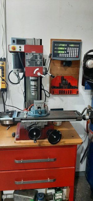
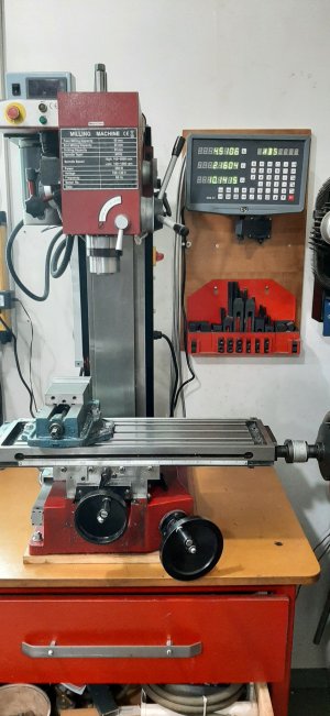
Well, there seems to be a lot of members installing DRO's lately. Figured I would throw another thread on here rather than hijacking someone else's. In a previous thread on DRO's, I had mentioned purchasing the system from AliExpress a couple of months back and it (the project) finally came to the top of the list. :)

The mill is a Sieg X3 aka Grizzly G0463 aka others. Others have documented their installs onto similar machines so I was lucky in that I had some reference material to use. Grizzly has an install manual, DROPros do a video on a very similar machine (although they skip the Z axis which I thought would be the hardest, hence I tackled it first, before my enthusiasm waned), and several hobbyists on various forums have documented their installs.

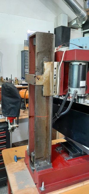
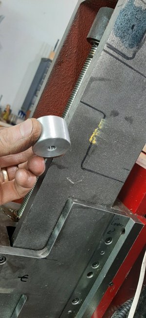
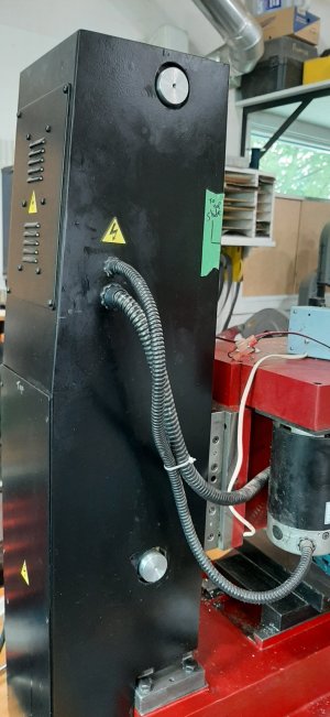
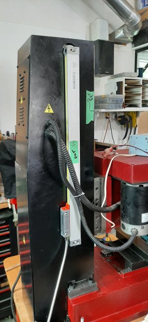
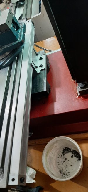
On this mill, the main column has a shroud around it, that also contains the electronics in the back part. One guy, who went to the column directly, removed the shroud and then never bothered to put it back. He was CNCing his machine and moved his electronics anyways. Others attached to the shroud, which I did not like. One guy actually put his inside of the rear column. Nice to keep it clean but when I looked at that, well, nope! So I compromised. I attached to the main column with spacers that brought the mounts out to the exterior of the shroud. It seems to have worked out so far. I like the look of it. I am in the process of connecting the head to the scale now. I will need or want to put a gasket around the holes for the spacers. That was the closest sized hole saw I had, but, honestly, I usually miss my alignment so wanted some wiggle room. As it turned out they are fairly centered so I am pretty happy with that. I started to make square mounts to match the scales, but then realized it would be way easier to use a round post. They are tapped M8 on the back side, holding the mount to the column, then M5 on the front to hold the scale to the mount. Both were turned to the same length so I am hoping that aids in aligning that axis, assuming that if the posts are within a thous and attached directly to the column, then the scale should be in the same plane, I hope. If not, this method allows shimming easily. My scales do not have grub screws like some of the nicer ones so shims it is.

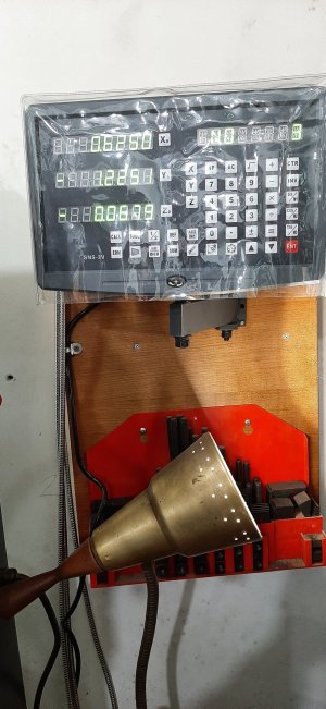
It is a bench top mill and my display goes on the wall so that works out OK. I am all excited just looking at it lit up. ;)

When I removed the shroud, I noticed how easy it would be to put a motor on the top of the lead screw (jack screw?) Maybe when I do the power feed, that option become one to be tackled.

Will report back tomorrow.
 

Attachments

  • 20220319_103710.jpg
    20220319_103710.jpg
    283.2 KB · Views: 26
  • 20220319_115739.jpg
    20220319_115739.jpg
    297.5 KB · Views: 26
  • 20220320_102742.jpg
    20220320_102742.jpg
    384.7 KB · Views: 24
  • 20220320_133552.jpg
    20220320_133552.jpg
    265.2 KB · Views: 24
  • 20220320_134941.jpg
    20220320_134941.jpg
    291.4 KB · Views: 26
Well, there seems to be a lot of members installing DRO's lately.

Love your Z Axis install.

Glad to see you didn't encounter any undrilobillium in your castings.

Ya, you don't need to worry about tackling the worst first. Once that first axis is working and the whole thing becomes real, you won't lose interest anymore. Feathering that axis, watching the numbers change, realizing its really where it says it is, finding center, adding dimensions and offsets, Calculating positions,....... And on and on and on. Ya, you will get it done......

I cannot wait to do the rest of mine!
 
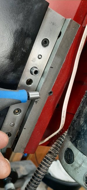
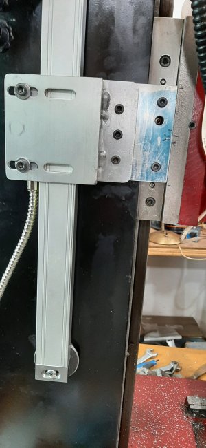
The Z axis scale install is complete. Instead of drilling and tapping holes into the head slide, I turned some bushings/standoffs and utilized some existing head mount screws. It worked out well. And a little welding for the bracket to attach the scale slide. I originally had some ideas about ways to connect the head bracket to the scale but this one won the internal debate. :rolleyes:

Yes @Susquatch watching that first scale install respond to head movements certainly lights the fire to get going on the other ones!

Started on the Y axis next.
 

Attachments

  • 20220321_141420.jpg
    20220321_141420.jpg
    338.3 KB · Views: 14
  • 20220322_140303.jpg
    20220322_140303.jpg
    276.5 KB · Views: 13
This project is complete. I did get to use it once while making one of the brackets. Yep, that will make my mistakes a lot more fun and accurate! :oops:

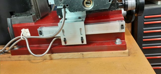
It was not as hard as I had thought (non of the undrilliabilium that @Susquatch had to deal with) I did take the table all apart to clean the surfaces up. I thought I had a centering issue with the x axis but turns out it is typical of those machines. The table slides more one way than the other but the ruler they mount on the front for a rough guide is centered, therefore, out 2 inches. Lost some time on that but in the end, all good.

Gotta go find a project now to test it out with! ;)
 

Attachments

  • 20220325_162911.jpg
    20220325_162911.jpg
    289.3 KB · Views: 14
  • 20220325_162955.jpg
    20220325_162955.jpg
    281.4 KB · Views: 13
  • 20220325_162937.jpg
    20220325_162937.jpg
    244.3 KB · Views: 13
This project is complete. I did get to use it once while making one of the brackets. Yep, that will make my mistakes a lot more fun and accurate! :oops:

It was not as hard as I had thought (non of the undrilliabilium that @Susquatch had to deal with) I did take the table all apart to clean the surfaces up. I thought I had a centering issue with the x axis but turns out it is typical of those machines. The table slides more one way than the other but the ruler they mount on the front for a rough guide is centered, therefore, out 2 inches. Lost some time on that but in the end, all good.

Gotta go find a project now to test it out with! ;)

Awesome job Shawn!

I just knew you would be done before me. My bride has me on a short leash doing slave duty. She arranged to have a bunch of friends over Saturday evening which she hasn't done throughout covid. So it's a really big deal for her. I slip out once in a while but can't do much more than drool.

Besides using the X-Axis to make the Y-Axis bracket and both X & Y to make the Z Knee bracket, I already know what my first DRO project will be - that spindle motor based Tool Post Grinder Holder. I had hoped to save a chunk of the aluminium for other projects but it won't be the end of the world if it all gets milled away and becomes swarf.

Unless of course a farm neighbour brings me a different project.
 
Nice looking finished product, Shawn.

You guys just keep pushing harder and harder for me to also get a DRO for the BP. It would make things a lot faster for sure.
Just checked again yesterday, the darn dials (and hence lead screws) are accurate to less than a thousand error over a two inch range on that old girl if I do my part on backlash compensation. This is going from either side of a center point out and then back to it. Can’t really beat that, I think. A DRO would take care of the little backlash error there is and free up some brain cells for other things I suppose…
 
A DRO would take care of the little backlash error there is and free up some brain cells for other things I suppose…

Yup. It will.

I did find some things I didn't expect though. Even with the axis locked, some feed pressure seems to result in a little axis movement I wouldn't have known about - but should have guessed.

I don't yet know how much of what the DRO says is real. I will be doing some tests after it is all working to see what's what.

But all in all, km totally thrilled. I am losing brain cells faster and faster as time passes so I don't need to wasting what I have left figuring out how to compensate for backlash all the time either. You will like it!
 
the DRO's 1/2 function saves my brain more than anything on the mill

@Susquatch , you have 1 micron scales, someone passing gas in the next room will make the reading change...

I have lots to learn. Best use of the 1/2 function is just one of them. It will be fun learning.

I ordered a better edgefinder for the purpose.

Yes, I have 1 micron scales. But I set the DRO to only display tenths of an inch. Doesnt seem to be a big problem even though it does show up when loading the milling tool. Doesn't bother me though. I know what it is and expect it. I can always set the dro to 3 digits if I want or need to.
 
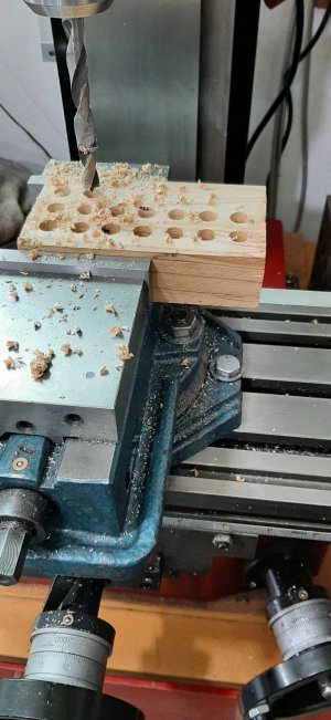
I am truly looking forward to the half function! But flipping through the manual the other night, and thinking of Blondiehack's video on DRO's (I hang out with her way too much!) I came up with an over engineered project to use the DRO for as a practice project. Each hole is 0.375 in diameter and 0.25" between them. The DRO can layout linear lines as stepped lines or do the math for you as a linear lines with X number of holes. I did the math and ventured into the stepped mode today. Took me longer to do the math and check, and check again.... than to actually drill the holes. That is a sweeeeeet function! Drill, step the increment to the next hole, drill......

My first real test of the DRO but it will be a very worth while investment of time and money!

I know, all you guys that have had them are rolling your eyes, but for those other new guys out there without a DRO, don't wait as long as I did. Jump in! You will not regret! :D

The most accurately drilled piece of wood in my shop, and beats most metal projects too! ;)

It is offset in the vice because of where I bolted the vice down. I did not realize I was beyond the center of the chuck. Stupid mill!:mad:
 

Attachments

  • 20220329_120016.jpg
    20220329_120016.jpg
    296.8 KB · Views: 10
  • 20220329_120031.jpg
    20220329_120031.jpg
    345 KB · Views: 10
It is offset in the vice because of where I bolted the vice down. I did not realize I was beyond the center of the chuck. Stupid mill!:mad:

Sorry Shawn, I don't understand the issue here.....

But very cool block. I'll have to try that too!
 
But did you first use an edge finder on the 2x4? LOL
I seriously could not live without my DRO. It just makes machining that much more enjoyable (and accurate).

Other DRO party tricks:
- turn dial to remove backlash, zero the dial, zero your DRO, spin off a couple hundred turns of the leadscrew returning to a zero mark. Compare to DRO reading. Ponder which is closer to the real displacement
- zero your DRO, keep the table locks off. Push & pull the table. Gasp with amazement that the display registers displacement yet the handles were not turned. No wonder that flux capacitor part was always +/- a couple thou. Say no more, with DRO!
 
Sorry Shawn, I don't understand the issue here.....

Just the position of the vise on the table. I thought I was well within the table travel limits when I bolted the vise down. Limited travel in the table. Easy to move of course but a pita to line up again. I figured a wooden practice block was not worthy of moving the vise. :D

But did you first use an edge finder on the 2x4? LOL

Maybe........;)....lol. Nerds be strong here!
 
Just the position of the vise on the table. I thought I was well within the table travel limits when I bolted the vise down. Limited travel in the table. Easy to move of course but a pita to line up again. I figured a wooden practice block was not worthy of moving the vise. :D


Maybe........;)....lol. Nerds be strong here!

I see. In that case, I'd be moving that vise. Ya gotta do it sooner or later!

Too funny on the 2x4 edge finder!
 
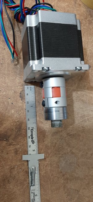
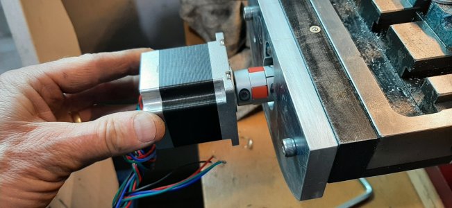
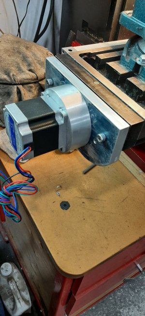
Got the DRO wrapped up. Moving on to the power feed. I have been working on the control circuit, using an Arduino for a stepper motor driver, but now moving onto the motor install. I bought a coupling similar to a lovejoy coupling so that there is a bit of room for slight misalignment. It might have been better to just mill the adapter for direct fit (that would have been really easy, actually) but I wanted a bit of flex. Sorry, not flex....I don't trust myself to get it perfectly aligned and with such a short adapter, figured the plastic drive center might not hurt....

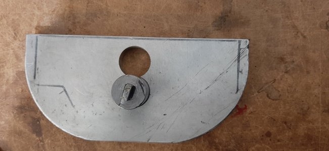
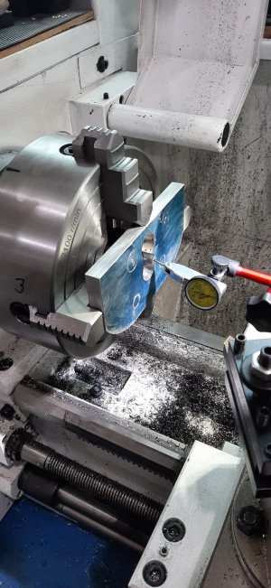
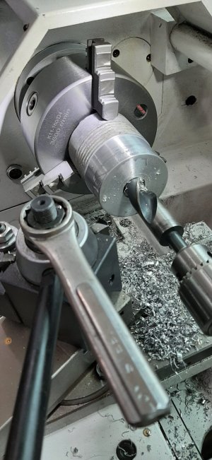
For the plate, I had this 1/2" piece of aluminum around for quite a while. It had the two holes in it, very close to where I would have wanted one of them. In hind sight, I probably should have started with the other end, but alas, live and learn. I put the plate in the 4 jaw and bored the hole that I was going to use out to a diameter that would safely accomodate the coupling, but missed a bit..:rolleyes: due to not paying attention so then the clearance hole got bigger, longer... (Why do I feel like I am in confession here when I post?..;) )

Once the coupling and adapter were done, I could determine the spacer requirement, which turned out to be 1 inch. Wondering what I could use, I realized that some coffee can aluminum might work. It did. So that is as far as I got today. I think it will look good and be functional by milling the motor mount as shown in the pdf. Will see how that adventure goes tomorrow. 20220406_111503.jpg20220406_125657.jpg20220407_142353.jpg20220407_142416.jpg20220407_153417.jpg20220407_164007.jpg
 

Attachments

Last edited:
Got the DRO wrapped up. Moving on to the power feed. I have been working on the control circuit, using an Arduino for a stepper motor driver, but now moving onto the motor install. I bought a coupling similar to a lovejoy coupling so that there is a bit of room for slight misalignment.

I think it's beautiful Shawn.

Great job!

I keep thinking about a power x axis too. But the price went to hell in a handbasket. So it has to wait a while.

I did make a drive nut for my Z-Axis so I can use a 20V Drill to raise and lower my table. I like that but still use the crank for fine adjustments. I'll prolly leave the Y as is.
 
Back
Top