I started to make a fixture plate for my 8” RT last year but finally (hurried up and) got it done in time to take it to the Ontario meetup. It generated some interest so I decided to show it here too.
These are an easy and inexpensive build that greatly increases the capacity of your RT and is significantly easier to manage (lighter) than a monster 12” RT (T slots would be nice in a fixture plate but this design is much easier and lighter).
It is 13.5” diameter because thats the largest circle I could cut from the old (rusty) piece of 5/8” plate that I had kicking around.

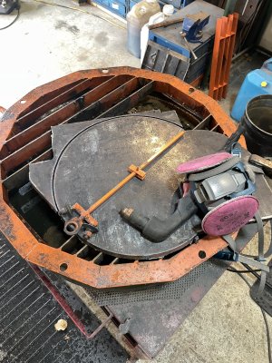
It was cut with the plasma cutter:
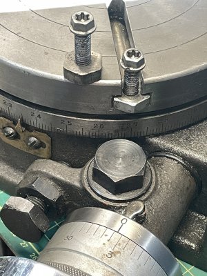
The plate is attached (bolted) to the RT via its T slots:
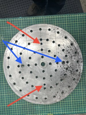
It is intended that one side of the new fixture plate will not be cut or damaged but the surface of the reverse side will be considered sacrificial.
In the next picture the blue arrows are pointing out the attachment bolt recesses when this side is up. The red arrows are pointing to the attachment bolt holes when the reverse side is being used (these holes have recesses on the other side).
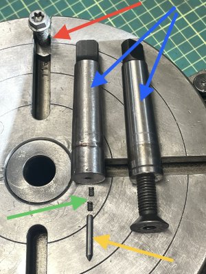
In the next picture the blue arrows are modified MT2 adapters that fit the centre RT hole. The adapters were milled to match the hole diameter in the fixture plate. It’s a tight fit, with less than 0.001” clearance and it needs to be wiggled and tapped to get the plate on or off (yes i did mill the adapter diameters because that’s what you do if you don’t have a lathe). Also in this pic - the red arrow is an attachment bolt in the RT T slot. The green arrow points out a pair of 1/8” dia springs, which along with the 1/8” dia pin (yellow arrow) are inserted into the 1/8” hole that is centred in the top of the MT2 adapter. The protruding tip of the pin makes it easy to center a part as long as you don’t mind giving the part a center punch mark.
Here’s another look at the locating pin:
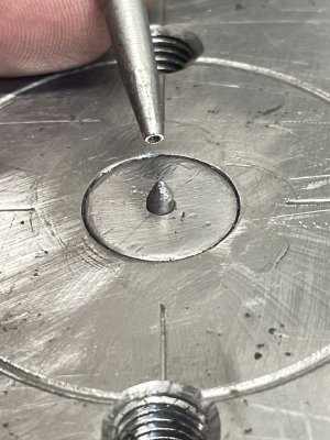
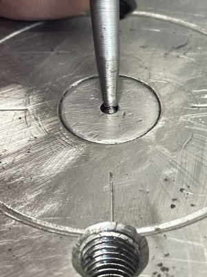
I milled a pair of angle brackets that can be bolted to the fixture plate. This gives a solid stop or pair of stops to help locate a part (or multiple parts) in the same location. On the outer ring of holes the two holes in the bracket line up with the 1st and 5th ring holes. Similarly these bracket holes also line up with the 1st and 7th hole in the second ring of fixture plate holes.
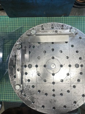
In above pic the machinist square shows that the brackets are at 90 degrees and are attached to the outer ring of holes. In the next pic I added some Prussian Blue grease to the brackets for improved visibility and replaced the machinist square with a plastic drafting triangle (green masking tape on the triangles for better visibility).
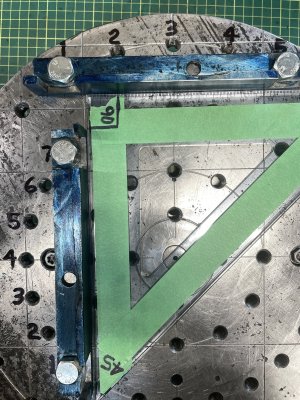
Note that in above pic the horizontal bracket is attached to the outer ring of holes and the vertical bracket is attached to the second ring.
The extra hole in the bracket works for the third ring of holes as seen here:
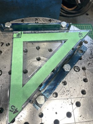
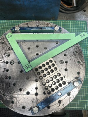
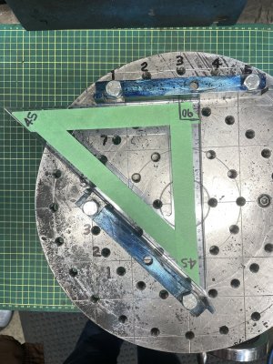
The angle between brackets can be set at 30, 45, 60, 90, or 120 degrees. Here’s some examples: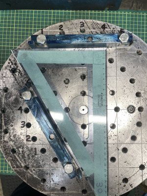
These are an easy and inexpensive build that greatly increases the capacity of your RT and is significantly easier to manage (lighter) than a monster 12” RT (T slots would be nice in a fixture plate but this design is much easier and lighter).
It is 13.5” diameter because thats the largest circle I could cut from the old (rusty) piece of 5/8” plate that I had kicking around.
It was cut with the plasma cutter:

The plate is attached (bolted) to the RT via its T slots:

It is intended that one side of the new fixture plate will not be cut or damaged but the surface of the reverse side will be considered sacrificial.
In the next picture the blue arrows are pointing out the attachment bolt recesses when this side is up. The red arrows are pointing to the attachment bolt holes when the reverse side is being used (these holes have recesses on the other side).

In the next picture the blue arrows are modified MT2 adapters that fit the centre RT hole. The adapters were milled to match the hole diameter in the fixture plate. It’s a tight fit, with less than 0.001” clearance and it needs to be wiggled and tapped to get the plate on or off (yes i did mill the adapter diameters because that’s what you do if you don’t have a lathe). Also in this pic - the red arrow is an attachment bolt in the RT T slot. The green arrow points out a pair of 1/8” dia springs, which along with the 1/8” dia pin (yellow arrow) are inserted into the 1/8” hole that is centred in the top of the MT2 adapter. The protruding tip of the pin makes it easy to center a part as long as you don’t mind giving the part a center punch mark.

Here’s another look at the locating pin:


I milled a pair of angle brackets that can be bolted to the fixture plate. This gives a solid stop or pair of stops to help locate a part (or multiple parts) in the same location. On the outer ring of holes the two holes in the bracket line up with the 1st and 5th ring holes. Similarly these bracket holes also line up with the 1st and 7th hole in the second ring of fixture plate holes.

In above pic the machinist square shows that the brackets are at 90 degrees and are attached to the outer ring of holes. In the next pic I added some Prussian Blue grease to the brackets for improved visibility and replaced the machinist square with a plastic drafting triangle (green masking tape on the triangles for better visibility).

Note that in above pic the horizontal bracket is attached to the outer ring of holes and the vertical bracket is attached to the second ring.
The extra hole in the bracket works for the third ring of holes as seen here:

The angle between brackets can be set at 30, 45, 60, 90, or 120 degrees. Here’s some examples:


Last edited:


