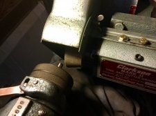
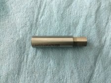
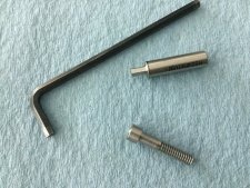
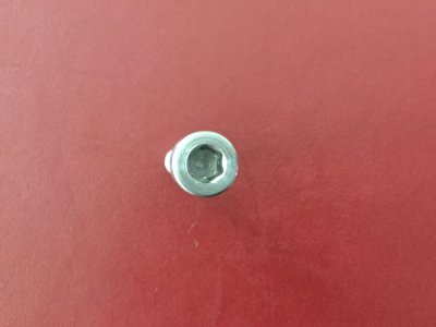
After having seen Randy Richard in the Shop and Stefan Gotteswinter build their Hemingway Kit rotary broaches, I decided to take a crack at making one.
First I went in search of some plans online and found one that I liked as a starting point.
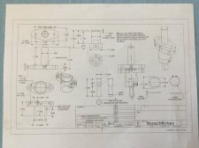
Then I had a look around the shop for parts and bits of metal that might be suitable to be turned into the various components. The live center (LC) on my lathe tool holder rack caught my eye. Perhaps one could base the broach on the same basic dimensions/functions? It has a rotating part held in a body which is attached to either a driver (like a milling machine) or held stationary like in a tail stock. So now I needed both MT3 and R8 shafts on the driver plate - not just the straight shank that I had originally planned. Well, looking around some more, I had one of each from boring heads that have screw-in adapters.
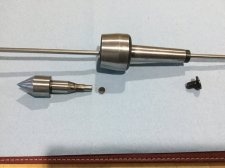
Here is the MT3 live center disassembled that served as a template for the rotary broach.
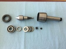
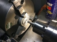
So if one took the LC spindle and made it hollow to accept cutting tools as shown below, that would be the tool holder taken care of... (4140 steel)
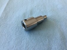
The basic dimensions of the tool holder are identical to the spindle from the LC. The tail is a little shorter to reduce the overall length of the rotary broach. I used the same three bearings as in the LC: one ball, one ball thrust, and the little roller for the end. The set screw hold the tools.
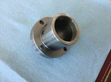
Next I made the body from a piece off of a 4140 log. The four holes on the flange are oversize for a 1/4-20 SHC to allow for adjustment of the tool point to the axis of rotation. That way it just wobbles, but has no run-out. The set screw is for oiling the bearings.
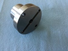
Here is the body from the back with the key way.
The body of the broach needs to be mounted at an angle to the center line (the drawing suggest 1.2*- I went with that). So I made the drive plate (also 4140) with a 1.5 in by 18 tpi threaded hole to accept the interchangeable adapters (MT3 and R8) and milled and ground the other face 1.2* off of parallel.
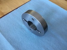
Note the corresponding key way to match the body's to transmit the driving forces using a square key.
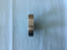
Here is a side view showing the 1.2* taper of the faces.
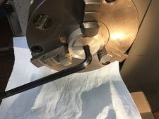
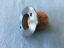
And to hold all the parts inside the body, here is a retaining ring with face spanner holes.
These are all the parts in one image. I did not make the arbours.
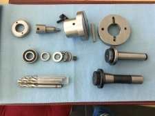
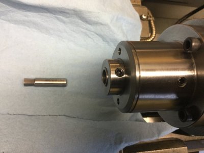
I have good supply of broken HSS drill bits and Carbide end mills from my daughter's work . I will be making broaching tools from them as I need them.
Lastly, the broach fully assembled.
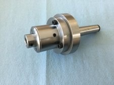
This was fun to build and I learned a lot. Now I just need to make a broach and try it out...
Another project off my very long list of things to do complete.
First I went in search of some plans online and found one that I liked as a starting point.

Then I had a look around the shop for parts and bits of metal that might be suitable to be turned into the various components. The live center (LC) on my lathe tool holder rack caught my eye. Perhaps one could base the broach on the same basic dimensions/functions? It has a rotating part held in a body which is attached to either a driver (like a milling machine) or held stationary like in a tail stock. So now I needed both MT3 and R8 shafts on the driver plate - not just the straight shank that I had originally planned. Well, looking around some more, I had one of each from boring heads that have screw-in adapters.
Here is the MT3 live center disassembled that served as a template for the rotary broach.

So if one took the LC spindle and made it hollow to accept cutting tools as shown below, that would be the tool holder taken care of... (4140 steel)

The basic dimensions of the tool holder are identical to the spindle from the LC. The tail is a little shorter to reduce the overall length of the rotary broach. I used the same three bearings as in the LC: one ball, one ball thrust, and the little roller for the end. The set screw hold the tools.
Next I made the body from a piece off of a 4140 log. The four holes on the flange are oversize for a 1/4-20 SHC to allow for adjustment of the tool point to the axis of rotation. That way it just wobbles, but has no run-out. The set screw is for oiling the bearings.

Here is the body from the back with the key way.

The body of the broach needs to be mounted at an angle to the center line (the drawing suggest 1.2*- I went with that). So I made the drive plate (also 4140) with a 1.5 in by 18 tpi threaded hole to accept the interchangeable adapters (MT3 and R8) and milled and ground the other face 1.2* off of parallel.

Note the corresponding key way to match the body's to transmit the driving forces using a square key.
Here is a side view showing the 1.2* taper of the faces.

And to hold all the parts inside the body, here is a retaining ring with face spanner holes.

These are all the parts in one image. I did not make the arbours.

I have good supply of broken HSS drill bits and Carbide end mills from my daughter's work . I will be making broaching tools from them as I need them.
Lastly, the broach fully assembled.

This was fun to build and I learned a lot. Now I just need to make a broach and try it out...
Another project off my very long list of things to do complete.

