• Scam Alert. Members are reminded to NOT send money to buy anything. Don't buy things remote and have it shipped - go get it yourself, pay in person, and take your equipment with you. Scammers have burned people on this forum. Urgency, secrecy, excuses, selling for friend, newish members, FUD, are RED FLAGS. A video conference call is not adequate assurance. Face to face interactions are required. Please report suspicions to the forum admins. Stay Safe - anyone can get scammed.

Reproducing feed arm

MecGen

Member
Hello friends

I would like to ask your opinion and get suggestions on how to tackle this. I have a "New All" gear box that is in great shape, mounted on my South Bend lathe. Before I purchased this machine, one feed arm was replaced with a a make shift type arm that simply is annoying to work with.

First and foremost option would be to find a used part, I have had notifications turned on for this on all the big sites, Ebay Kijiji and Craigs, with no avail. I am sure its really rare. Buying a complete feed gearbox is an option, but what I find is old junk at a huge price with an unrealistic shipping cost.

So I was looking at getting this part reproduced. Maybe 3D scanning and CNC machined? I have no experience in this or even where to look for this service, and maybe even harder to find a shop that would do me a one off. Why do I get the feeling this would cost more then I paid for the lathe, I don't mind paying a couple hundred just not a thousand. I find used gearboxes for around $200-$300 USD.

Does anyone have any ideas? Know of a place that has 3D equipment? Should I just try a better repair?

Thanks in advance
08384175db92fdb60d258671eb047571.jpg
2f8574e517cfe935cc8b55fa4c4ecc87.jpg
cf3e23338aeda0b6e4a3df2c1eb9ad64.jpg


Sent from my SM-T590 using Tapatalk
 
I take it that the sleeved arm is a pain....seems like machining a new "repair section" and then joint it to the original bottom part by pining it - then weld or braze and shape back to original at the repaired section?
 
X2 what Brent said. I think Keith Rucker did a similar repair in one of his videos. Sorry can’t find it right now.
 
The top part is just a piece of round that you can fit out with a spring and pin and knurle up the handle - weld on a properly bent piece of steel round that matches the original diameter, joint to the old bottom piece and weld/braze to make permanent. It does take a few different processes....
 
From your pic I could trace a 2D CAD pattern of the casting outline with the idea you hand off to a water/laser cutter & make from stock, say 0.75" or whatever suits. From there it would still require you/someone machining the holes & recesses etc. The shanks & arms wouldn't be round like the casting but maybe simple 45-deg chamfers would suffice? Even these 2D oultine cutting services have a min fee so wouldn't surprise me if getting a pair or more same time is same cost. At least you would have a file format you could send out to service for quote.

I don't know a ton about making parts from3d scanned (point cloud) data but I think more CAD intensive on the front end. Someone has to make sense of the data meaning honour critical actual dimensions & ignoring/smoothing non-critical points before handoff to the CAM guys. Essentially redesigning the part & using the scan as close guidance. I suspect $$.

Unfortunately yet another example where casting things back in the day, even intricate shapes, was just so much more prevalent & cost effective than today because low volume custom casting services are few & far between.

1612029291995.webp
 
If it were mine I’d cast one out of aluminum . Probably cast two to have them match

It’s symmetric so you have a good parting line

Send me a wood pattern and I’ll cast one for you. It would basically be a blank and you’d have to machine the bores etc


Sent from my iPhone using Tapatalk
 
I take it that the sleeved arm is a pain....seems like machining a new "repair section" and then joint it to the original bottom part by pining it - then weld or braze and shape back to original at the repaired section?
X2 what Brent said. I think Keith Rucker did a similar repair in one of his videos. Sorry can’t find it right now.
The top part is just a piece of round that you can fit out with a spring and pin and knurle up the handle - weld on a properly bent piece of steel round that matches the original diameter, joint to the old bottom piece and weld/braze to make permanent. It does take a few different processes....
This is what I am leaning to, I have a Tig but I just bought it so I would need some help on a brass silicone weld. I will take another picture when I get to the shop later, this arm has more than one joint with makes it sloppy as hell.
Thanks for the input

Sent from my SM-T590 using Tapatalk
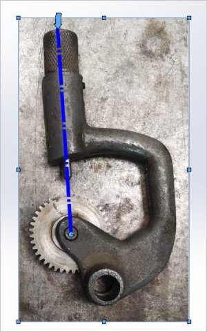
 
From your pic I could trace a 2D CAD pattern of the casting outline with the idea you hand off to a water/laser cutter & make from stock, say 0.75" or whatever suits. From there it would still require you/someone machining the holes & recesses etc. The shanks & arms wouldn't be round like the casting but maybe simple 45-deg chamfers would suffice? Even these 2D oultine cutting services have a min fee so wouldn't surprise me if getting a pair or more same time is same cost. At least you would have a file format you could send out to service for quote.

This would definitely be an option, .75 or even .5 would work as I would be making a spring pin anyway (depending on stabilityof the arm on shaft). Rounding the edge by 45° is perfect, I was willing to smooth out stuff by hand.

I don't know a ton about making parts from3d scanned (point cloud) data but I think more CAD intensive on the front end. Someone has to make sense of the data meaning honour critical actual dimensions & ignoring/smoothing non-critical points before handoff to the CAM guys. Essentially redesigning the part & using the scan as close guidance. I suspect $$.

My hopes were to give the good arm to a guy/shop that has a hand held scanner, get itscanned- transfer the data to super computer, then cuts me a perfect replica with a cnc ... thats how it works on Star Trek, are you saying its not that simple? ;)

Thank you

Sent from my SM-T590 using Tapatalk
 
Unfortunately yet another example where casting things back in the day, even intricate shapes, was just so much more prevalent & cost effective than today because low volume custom casting services are few & far between.

If it were mine I’d cast one out of aluminum . Probably cast two to have them match

It’s symmetric so you have a good parting line

Send me a wood pattern and I’ll cast one for you. It would basically be a blank and you’d have to machine the bores etc

Getting one cast is an option that I informed about, people related to the foundries seemed to think I needed to find someone in a private shop (at home or whatnot) because full scale foundries won't look at a small project like mine.
I was thinking of getting it casted from Iron but I can't see why aluminum wouldn't do the job. I cou.d make a blank from a piece of wood...

Food for thought, I will think about your offer Kevin, I would private message you for the cost.

Thanks again for taking the time, much appreciated


Sent from my SM-T590 using Tapatalk
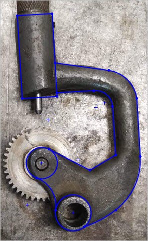
 
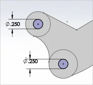
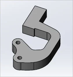
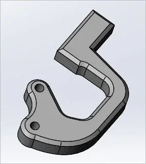
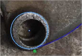
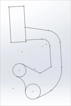
This pictorial is only intended as general FYI but hopefully demonstrates the general workflow: Background picture > Cad tracing > Cad manipulation > 2D blank cutout. In reality, it still takes specific knowledge about the part itself, specific dimensions etc. You can see photo resolution & parallax issues can cause issues, it will rarely be a button click automated process. And even with a blank of steel cut with water/laser, now the actual machining operations commence. 3D scan is even more fun. Generally its quicker to design the part in 3D from scratch & just ensure its dimensionally compliant with the original part. Notice this 'flat stock' does not have the raised axle boss like your part.

If you could blank off the axle holes & bosses with wax or removable putty, maybe you could use one of your existing parts as a (foundry) pattern. Or like some guys are doing, get a 3D plastic part printed & use that. Its not a trivial project.
 

Attachments

  • SNAG-1-30-2021 0001.jpg
    SNAG-1-30-2021 0001.jpg
    50.1 KB · Views: 3
  • SNAG-1-30-2021 0002.webp
    SNAG-1-30-2021 0002.webp
    16.1 KB · Views: 3
  • SNAG-1-30-2021 0003.jpg
    SNAG-1-30-2021 0003.jpg
    42.1 KB · Views: 3
  • SNAG-1-30-2021 0004.webp
    SNAG-1-30-2021 0004.webp
    5.8 KB · Views: 4
  • SNAG-1-30-2021 0005.webp
    SNAG-1-30-2021 0005.webp
    5.2 KB · Views: 4
  • SNAG-1-30-2021 0006.webp
    SNAG-1-30-2021 0006.webp
    4.7 KB · Views: 4
  • SNAG-1-30-2021 0007.webp
    SNAG-1-30-2021 0007.webp
    8.7 KB · Views: 3
This pictorial is only intended as general FYI but hopefully demonstrates the general workflow: Background picture > Cad tracing > Cad manipulation > 2D blank cutout.
Its not a trivial project.

Ok I get this, more complicated then it looks, but I understand better the process. I guess I will look into repairing this part better.

Thank you


Sent from my SM-T590 using Tapatalk
 
If there are any foundries close by, you should check directly with them. You might be surprised. Further away there are some Amish foundries in the NE States that would likely do it for you.
 
Back
Top