• Scam Alert. Members are reminded to NOT send money to buy anything. Don't buy things remote and have it shipped - go get it yourself, pay in person, and take your equipment with you. Scammers have burned people on this forum. Urgency, secrecy, excuses, selling for friend, newish members, FUD, are RED FLAGS. A video conference call is not adequate assurance. Face to face interactions are required. Please report suspicions to the forum admins. Stay Safe - anyone can get scammed.

Repair + Calibrate Mitutoyo Bevel Protractor

jmottle

Member
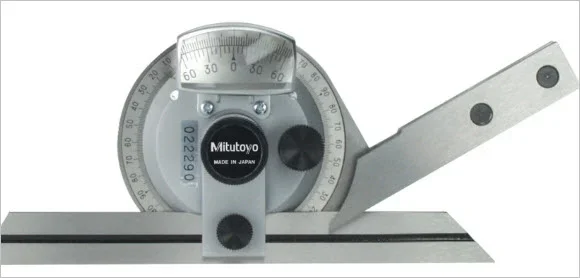
So I purchased a Mitutoyo bevel protractor off Kijiji today. Saved about $225 off retail, so thought it was worth it. The fine adjustment gear did not work but I managed to fiddle with it to get that working. I think it's off by about half a degree in accuracy using some gage blocks and the edge of my precision vice to test, but I'm not sure. Any thoughts on how I get this re-calibrated and get the the acute angle attachment? Is there anyone local (Calgary) that can do this or does it have to be shipped back to Mitutoyo?
Thanks!
 
Last edited:
I bought a new Mitutoyo dial indicator from Thomas Skinner Calgary last year that I thought didn't feel right out of the box. You know when you push the plunger in & it immediately springs back. This one seemed sluggish. Very smooth, always returned to exactly zero, but sluggish. I returned it & they sent it to 'Mitutoyo service' wherever that is because it was under warranty, but I got the impression either local rep or Canada for sure. You might want to give them a call for a lead. I suspect they probably won't administer it for you, but at least could give you contact information. There is a Mr. Precision Instrument Guru I always hear about on a USA forum but maybe more $ back & forth.

Oh & my DTI, it was a 0.0001" grad & checked out fine. I guess the higher res ones have that much more gears & Klockenschpringz in there so a bit more sluggish is perfectly normal.
 
Thanks. Looks like there is a repair facility in Ontario, so I'll call them on Monday to see what might be involved. Hopefully does not cost too much.
 
Is it like this kind? I don't have one but just curious. When you say fine adjustment gear, do you mean a knurled knob that fine tweaks the angle, or there are truly gears in the head assembly?

I'm also curious how you did your test with gage blocks & a vise. If there is a way to set the protractor on a good flat surface, you should be able to use the extended arm length to your advantage. A 0.5-deg angle difference equates to .052" rise over a 6" distance (just as an example). So that gap distance is something you could measure very accurately. Or alternatively, measure across 2 different rounds like a 0.25" and 0.375" end mills at a fixed known distance apart & calculate measured angle vs. geometry angle to get error. I can make you a sketch if this isn't clear.
 

Attachments

  • SNAG-3-17-2018 0000.webp
    SNAG-3-17-2018 0000.webp
    11 KB · Views: 5
Yes. that is the one. To the right of the center lock down knob is the smaller black knob. The end of that shaft has a small gear that sync with a larger fixed brass gear behind the rotating assembly. Because it was not working properly I had to pull it apart and is why I know this. It's also how I got it working again. The whole assemble is a bit finicky as the internal "fixed" brass wheel has to have a very slight amount of play or it will bind when you turn the assembly.

The test I did with my gage blocks was on 90 degree edge of a 3" block, but I guess this is not a great test as blocks are not used for their side to side tolerances. I did the same on the jaw of my milling vise. I assumed the tolerance on that would be high, but again, maybe not a good test. I could use the bed of my vise to measure 180 degrees as that would be milled very accurately. That's only a 4" width though. I'm not sure I follow your example entirely. I'm trying to picture how to set that up.
 
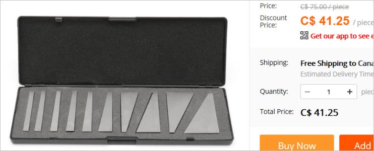
I have some of these cheapy angle blocks. They are very useful for setting things in the vise or mill table at specific angles. You could directly read the block angle & probably eliminate 2 or 3 of your setup variables (datum surface / gage block stack / vice datum block). Of course, now how accurate are the gages themselves? My $40 set came with a signed 'inspection certificate' so of course I would bet my life on it (LOL). Generally the Chinese sets are pretty decent, at least within limits of what you are likely to hold in actual machining.

The 2-pin measurement method is like this sketch. The bottom dash line is your datum surface. The solid line on the top is tangent to 2 rounds (dowel pins, end mills, anything that is known accurate). That line represents your angle blade resting on top. I'd have to work out the formula but basically input Dia1, Dia2 & Distance & compute angle. Compare that to what your unit reads. The longer the distance, the more accurate the measurement. You will be within hundredths of a degree with any reasonable distance.
 

Attachments

  • SNAG-3-17-2018 0001.webp
    SNAG-3-17-2018 0001.webp
    6.5 KB · Views: 4
  • SNAG-3-17-2018 0002.jpg
    SNAG-3-17-2018 0002.jpg
    34.4 KB · Views: 8
  • SNAG-3-17-2018 0003.webp
    SNAG-3-17-2018 0003.webp
    8.3 KB · Views: 8
Ahh got it, thanks! Love this forum. So much more friendly than say PM. LOL. I am placing an order for a ton of new tools and gear at KBC, to set up my home shop, on Monday and I have an angle block set in there, so I'll use that to verify the setup. Not sure why I did not think of that. Still super new to all of this. Next week finish up my MACH 213 class at SAIT. Can't remember the last time I've had this much fun!

Going to purchase a Premium membership now. Running an online community myself full time in architecture, I appreciate the work it is for top members and the site owners to run a place like this.
 
The 2-pin measurement method is like this sketch. The bottom dash line is your datum surface. The solid line on the top is tangent to 2 rounds (dowel pins, end mills, anything that is known accurate). That line represents your angle blade resting on top. I'd have to work out the formula but basically input Dia1, Dia2 & Distance & compute angle.

The calcualtion is as follows (from Machinery’s Handbook, 29 ed, pg 684)

“Let K be the difference in the disk diameters divided by twice the center distance: K=(D-d)/(2C), then angle alpha = 2arcsinK”

In PeterT’s example the center distance is 4 9/16”. So K = 0.0136986. Solving for angle alpha gives us 1.56979* (the value he has on his drawing)

I guess with CAD, it computes it for you...
 
Last edited:
Back
Top