• Scam Alert. Members are reminded to NOT send money to buy anything. Don't buy things remote and have it shipped - go get it yourself, pay in person, and take your equipment with you. Scammers have burned people on this forum. Urgency, secrecy, excuses, selling for friend, newish members, FUD, are RED FLAGS. A video conference call is not adequate assurance. Face to face interactions are required. Please report suspicions to the forum admins. Stay Safe - anyone can get scammed.

Old motorcycle projects

John Conroy

member
Premium Member
I have been doing a project bike every winter for the last few years, this year it will be a Yamaha XS650SE. I bought it locally and it is a bit of a turd right now with the frame painted yellow. It took a bit of work to get it running, both carbs were in rough shape, the valves and cam-chain were badly mis-adjusted and of course the points and timing were also all wrong. A day of work and it now runs not bad with qualifies it to become a project. If the engine was toast I would have just parted it out.
My first project from quite a few years ago was a Honda CL450 which I wound up spending more money on than I should have, familiar story. Here is the finished bike.

P7250081.jpg


Next year it was a DT250. Here are before and after pics.

PB210500-Copy.jpg


P3270453.jpg


P3270454.jpg


Then came the money pit Kawasaki H1D. This bike is complete but waiting for paint.

P6050149.jpg


P6050153.jpg


P6050152.jpg


Then my favorite, a Kawaski A7 350. It is complete except for the seat.

P9100615_zpsd5a2bfcd.jpg


P8200350_zps59165de4.jpg


P8200357_zps6de6f9f6.jpg


Here is the XS

P9170232_zps4deee57b.jpg


P9170222_zpscefc3409.jpg


These projects are one of the reasons I got into machine work, so I can make my own parts when required.
Cheers,

John
 
I have decided to do the Yamaha XS650 up in street tracker style.
I bought a used front wheel from a 80 XS110 to use as the rear for my project. I am going to build my own sprocket and brake rotor mounts. I have started with the sprocket side, I machined a sprocket starting with a 530 sprocket blank purchased from Princess Auto. I used 12mm dowel pins between the teeth to mount it in the lathe and milling chucks. I bored the center to 2.516" to be the same size and the brake rotor mount on the wheel. Then added the bolt holes using an 80mm center hole circle and 6 decorative holes to resemble the original sprocket. Then I coated the exposed bare metal areas with a black oxide finish. I machined a sprocket spacer from a 4.5" round of aluminum I bought as a scrap end at Metal Supermarket.

P9200252_zps2207e3b9.jpg


P9210277_zps4fd17921.jpg


P9210273_zps9262fcdf.jpg


P9210266_zps29be78fb.jpg


P9210267_zps5e2f07b5.jpg


P9200255_zpsbe33bf47.jpg


Here are the plans I drew to plan the machning of the spacers.

16inchwheeldrawing_zps72120beb.png


19inchwheelspacerdrawing_zps1f6ec48d.png


John
 
Over the last few days I have finished machining all the parts for my 19" rear wheel conversion. It will use three 6204 bearings, the 2 in the original locations in the wheel and a third in the sprocket side spacer to help deal with the extra load on that side of the wheel. Here is a pic of the sprocket and rotor spacers and the one I machined to go between to 2 wheel bearings.

P9230296_zps2fcbd04a.jpg


I warmed up the spacer with my heat gun to 175 deg F and the bearing just dropped right in.

P9230298_zps63d10753.jpg


I machined another spacer to go between the left wheel bearing and the sprocket spacer bearing.

P9230303_zpsb80875d3.jpg


P9230308_zpse24029db.jpg


Here is the wheel assembly assembled to mock up in the frame.

P9240324_zpsff7d615e.jpg


P9240326_zpsff7c9a87.jpg


I clamped a straight lenght of 1/2" square aluminum to the front sprocket in order to space the wheel correctly for chain alignment then measured and machined the 2 outer spacers from stainless steel.

P9240329_zps330b15fe.jpg


P9270335_zps0f5b5e98.jpg


P9270337_zps03b3190c.jpg


I mounted the front wheel to check alignment front to rear with 2 straight lengths of lumber and it turned out spot on.

P9270338_zps8fd65fef.jpg


P9270342_zps4747c7ac.jpg


P9270343_zpsfca936a2.jpg


Now that the machine work is done I can pull the engine and get at the rest of the project.

John
 
The used 19 inch wheel I bought came with 2 slotted 300mm front brake rotors. The original single front 300mm rotor and the rear 270mm rotor are not slotted. I plan to use dual front brake rotors and they will be the slotted ones so I decided to match the slot pattern from the front rotors on the rear one. I mocked up the first slot and spot drilled the center and both ends of the slot to get locations on the DRO. With the rotor mounted in an extra hub I made and in my Vertex super spacer I copied the location at 60 degree spacing around the rotor and drilled all the holes to 8mm the slotted them with a 1/4" end mill. The stainless rotors are pretty hard so it was slow going but turned out well. After the slotting I mounted it in the lathe and use 320 grit sand paper to polish it up a bit.

P9280352_zps86055ccc.jpg


P9280351_zps9ba00e15.jpg


P9280353_zps781ae06c.jpg


P9280355_zps4444e747.jpg


P9280356_zps5afd4e0a.jpg


P9280359_zps7a445667.jpg


John
 
I had a few broken bolts to deal with on the engine. One of the starter motor mount bolts was broken flush with the case. I mounted the lower crankcase on an angle plate and set it level in the vise and used a 1/4" end mill to remove all of the bolt except what was in the case threads. The ran a tap into the hole to remove the remainder. It worked out nice with the threads still in good shape. I had to do the same on the cam cover for one of the point housing bolts.

PA180446_zps9987cd5c.jpg


PA180450_zps6c56d40a.jpg


PA180452_zps47afd9a8.jpg


PA180451_zpsc3906366.jpg


PA180458_zpsc2487575.jpg


PA180459_zpse1d37af9.jpg


PA180461_zpsc150bdd7.jpg


PA180462_zpse52395f9.jpg
 
awesome build up so far. Love the creativity like using a front wheel for a back wheel. I'm on the hunt for parts for my winter project. It is a 1985 yamaha XT550 that I have been riding for a month now and want to fix up. Keep posting your progress that thing looks great.
 
Nice work, John! Can't wait to see what you do with the XS. The 650's are awesome motors and there is a ton of support for them. Lots of guys build "bobbers", cafe's, or trackers out of them. You can even buy ready-built race motors for them. My project once the garage is ready will be an old Jawa 350.

Sent from my B15 using Tapatalk
 
very nice. I'm in to motorcycles too.my main project right now is a café racer 81 Gold wing. We machined fork extensions to mount the clip on handlebars to. turned out very very nice. That's what made me buy my own lathe. I bought a couple exit DW 650s but then realized I didn't need five project bikes so bailed on them but nice to see someone with one.
 
AWESOME!

Great write up and pics.

What do you do to finish the motor cases off.....chemical cleaning then powder coating then reassembly?
 
Thanks guys, all the engine parts get soda blasted or glass beaded then painted with Duplicolor engine enamel and baked at 250 degrees for 2 hours. It's a very durable finish.
 
Thanks guys, all the engine parts get soda blasted or glass beaded then painted with Duplicolor engine enamel and baked at 250 degrees for 2 hours. It's a very durable finish.

Thx John.

So the Duplicolor doesn't chip or flake off? Durable - similar properties to powder coating??
 
I recently picked up a couple of Buell project bikes, a 99 X1 which I am now riding daily and a 98 S3 which had no engine. The S3 has a nice set of 54mm WP upside-down forks that I could sell but I thought they would work on my Yamaha XS650 project bike. I mocked up the triple clamps from the Buell onto the Yamaha and liked what I saw so I decided to go ahead and try to make the swap work. I haven't decided yet if I'm going to use the 19" Yamaha wheels or the 17" Buell wheels, that will depend on what I come up with for the rear suspension. Here is the XS650 frame mocked up with the Buell triple clamps, forks and front wheel.

20160719_100417_zpsnbk85jxs.jpg


The Buell fork legs are 2" shorter than the XS forks so they will need to be extended, also the 17" wheel would put the bike 1" closer to the ground than the 19" ones.

20160725_082434_zpslmmrtcgn.jpg


20160725_082429_zpsb05przrw.jpg


I decided to make up a pair of 3" extensions like these ones from Extreme Creations.

http://www.extremecreations.com.au/post/2013/05/01/Hayabusa-fork-extensions.aspx

0000092_suzuki-fork-extensions_zpskbm9hojo.jpg


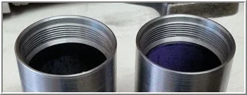
I decided to use some thick wall high strength steel tubing instead of the aluminum ones from EC, just because it was what I had on hand. The fork OD is 2.125" and the ID is 2.00" and the steel tube I have is 2.5'OD and 2.0" ID. The thread required is 49mm X 1.5mm pitch. I made up 2 three inch long outer tube extensions with a male thread on one end and female on the other.

20160728_105932_zpslmk847bj.jpg


20160730_150739_zpslgpyeq0x.jpg


20160730_150753_zps9zchjnym.jpg


The internal dampers in the fork will have to be moved up 3" as well so I made up a couple of 3" damper assembly extensions from some 1" 6061 aluminum I had on hand.

20160727_134921_zpsdvdx9unh.jpg


20160727_134942_zpsjvk9wsdk.jpg


20160727_140922_zpscnrnzaj3.jpg


Before I install them on the forks I'm going to color them with gun blue but they thread on very nicely and the O-rings on the original caps fit perfectly into the top of the extensions.

20160728_134426_zpshxinkagb.jpg


20160727_105510_zpsjbs9flxp.jpg


The triple clamps will need work to be retrofitted so that's the next thing on the list.

John
 
John, I don't know anything about bikes, but sure enjoy your build pics.
What are your tooling weapons of choice for external & internal threading jobs like these tubular parts?
Are these metric threads to match (Japan?) based bikes?
 

Attachments

  • 7-31-2016 0000.webp
    7-31-2016 0000.webp
    9.4 KB · Views: 4
Thanks Peter. Most of the threading I do is external and I use a carbide insert tool that covers most of the sae or metric thread sizes for my projects. Carbide insert tools are nice but they don't like turning at low speed and I do all my threading at 70 rpm so I have to take very light cuts and it can be time consuming. Not a big deal for me, these are fun projects. I have gotten the best results when using "Tap Magic" tapping fluid for lube on this low speed thread turning, it makes a much better finish that the other cutting fluids I have used. For the internal threading on this job I used a cheap cemented carbide tool and again very light cuts at 70 rpm. The same 60 degree tool I have used for most of the internal threading I have done. I alway use a tap for internal threading if I have the right size but this 49mm thread was very unusual. I looked up the thread dimensions in my Machinery Handbook for 1.5mm thread pitch and the difference between major and minor diameters is .082" for all the small metric fasteners that use that pitch. That seemed to match the dimensions I measured on the internal and external threads I measured on this set of forks so I went with a .041" depth with the cutting tools and it matches the existing threads perfectly. I had to switch the transposing gears on my lathe for metric threading and could not use the threading dial. I had to keep the feed screw engaged through the the entire process of each thread and stop the lathe at the end of each pass and back it up by backing the tool out with the cross slide and reversing the motor to back up for the next pass. Tedious but it worked.
 
This is really cool. I am impressed that you were patient enough to pull this off on an imperial lathe. It would have been tricky. The end result is cool stuff
 
I wanted to replace the ugly old rusty chrome front engine mount on the XS650 project bike. I stole this design from another member of the XS650 Forum. The only welded part will be the large washers attached to each plate at the engine. This is an image provided by Ristis on the XS650 forum.


front%20mount_zpsindei8qf.jpg


I’m going to use metal I have on hand, not stainless like Ristis did. I started with the old mount and clamped it to the mill table with the bolt holes vertical. The holes are 10mm and I have some pieces of 10mm drill rod that are a perfect fit so I used one of them to locate the holes and plot them on my DRO.


20160903_155158_zpsnp1llyzj.jpg


With the holes plotted I drilled three 10mm (.390”) holes in a piece of 5/16” plate steel and checked the fit with 3 lengths of drill rod and they lined up perfectly with the old mount.


20160903_201628_zpsgnpiiabc.jpg


20160903_202904_zpsxvln1e85.jpg


Then I drew a rough outline around the bolt holes to mimic the shape of the original mount, my goal was to leave at least ½” from the edge of the holes. I cut it out using my Portaband saw on a vertical stand I built.


20160903_205741_zpscfergvog.jpg


I set the piece up in the vise using the drill rods to get the holes horizontal and milled all 3 sides flat with equal spacing from the edge. Then test fit it on the engine/frame.


20160903_210239_zpswrdsbihb.jpg


20160903_214352_zpsmvzj5htn.jpg


Perfect fit. Then I just had to make another one and use the first one and drill rods to mill them both the same.

20160904_084743_zpsvpmy5h4t.jpg


20160904_092654_zpsjlocuxyz.jpg


20160904_092900_zpssyy5nwmi.jpg


Then I mounted both pieces on my rotary table and made a radius on all the corners.


20160904_100908_zpspvumfkqr.jpg


20160904_103842_zpsg68c0u9s.jpg


20160904_104128_zpsiwldb4rt.jpg


I installed the bolt through the engine cases and tightened it so I could measure the space between the plates and frame tube to make the outer spacers. The left side measured .590” and the right is .555”. I enlarged the 2 holes to the frame portion to .625". I machined 2 spacers for the left side with .590” of .980” diameter and .600” of .626” diameter. The .626” part is a .001” interference fit into the plate and the center spacer. I pressed the spacers into the plate and test fit the parts. Perfect so far.


20160904_144710_zpspciwbot6.jpg


20160904_144719_zpsz1bxiuul.jpg


That’s it for today.


John
 
I got the engine mount finished. I decided to add some decorative holes to the plates and I spot welded a washer to each plate to fit against the engine. I dressed the spot welds off on the belt sander. I machined 3 spacers, one for each side and one to go between the plates.

20160905_091906_zps21mtyn26.jpg


20160905_100521_zpslxbt1ksw.jpg


20160905_100526_zpsbt7q7fv5.jpg


20160905_103828_zpsderkk9wr.jpg


20160905_150152_zpsiwdsvkfy.jpg


Then I pressed all the part together in my Yost vise with aluminum jaws.

20160905_160415_zpsliaysukm.jpg


The finished mount fits like a glove and looks a lot better than the original I think.

20160905_161142_zpsaeiezf0y.jpg


20160905_161149_zps8qugls4f.jpg


20160905_161201_zpsgprcf81o.jpg


20160905_161207_zpsgndrfcxz.jpg


John
 
Back
Top