• Scam Alert. Members are reminded to NOT send money to buy anything. Don't buy things remote and have it shipped - go get it yourself, pay in person, and take your equipment with you. Scammers have burned people on this forum. Urgency, secrecy, excuses, selling for friend, newish members, FUD, are RED FLAGS. A video conference call is not adequate assurance. Face to face interactions are required. Please report suspicions to the forum admins. Stay Safe - anyone can get scammed.

New to me lathe

Colten Edwards

Fabricator
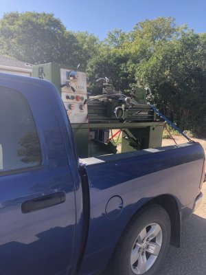
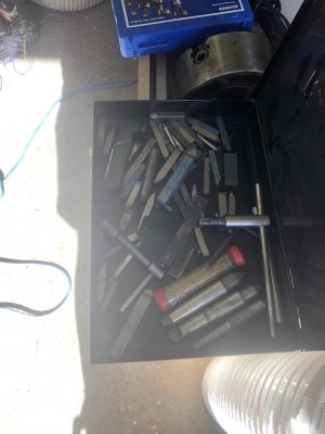
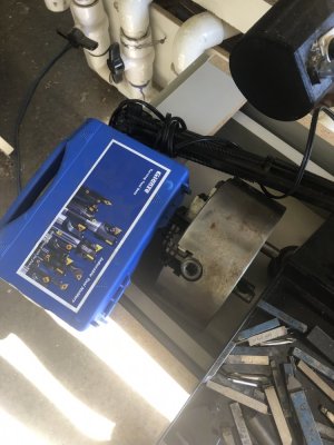
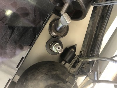
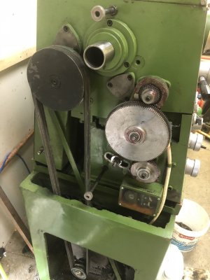
finally bit the bullet and bought a lathe today. It's a C6236 Force International (ie HoT fame). Price wasn't bad.. Didn't think the truck was going to work though.. Came with some tooling. though, there is no steady rest or follow rest.. I'll have to keep an eye on fleabay to see if something comes up.
 

Attachments

  • IMG_0146.jpg
    IMG_0146.jpg
    124.6 KB · Views: 41
  • IMG_0147.jpg
    IMG_0147.jpg
    80.1 KB · Views: 39
  • IMG_0148.jpg
    IMG_0148.jpg
    111 KB · Views: 32
  • IMG_0149.jpg
    IMG_0149.jpg
    114.2 KB · Views: 34
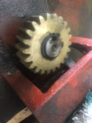
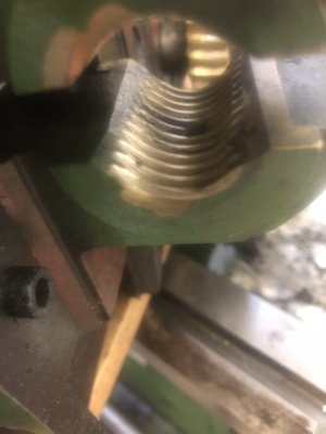
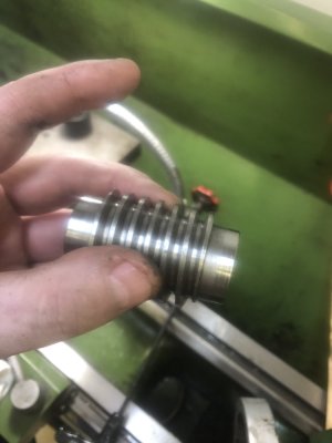
looks like I have a bit of a lemon. Feeds work well. No problems with it. Screw cutting will be an issue. As it feeds, you can see the handle pause slightly every time around. You can also feel something wanting to tick the handle. I'll try and upload a video later to show what I mean.. I'm also missing the 3 change gears I would need todo some threads. I just know it should have come with 3 gears and I got none. Looks like a 40, 45 and a 50T gear. Anyone know if Grizzly ever had a GH1440 model lathe? Pretty sure the G0709 or G4002 won't work for parts. I have sent a request to Warco and another to a chinese dealer asking about parts. We'll see what they say
 
I'll wait for the vid, but what handle? You mean the lever that engages the threading clamshell onto the threading lead screw?
 
Your lathe is likely different than my 14x40 but I would check

- The threading lead screw. Are there damaged threads it keeps tripping on every rotation? Is the lead screw rotating freely without power or does it wobble (ie. bent slightly)

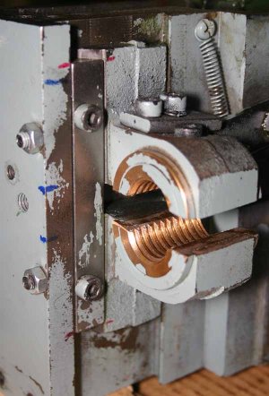
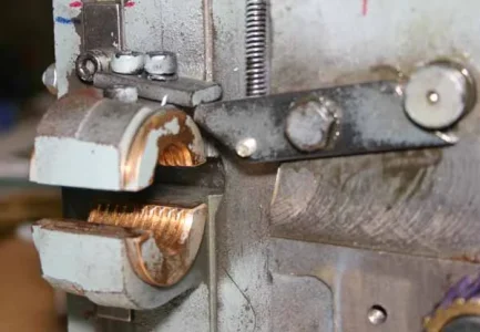
- Condition of the clam shells (mine requires apron removal to examine). If internal threads were nicked or badly worn or out of alignment or embedded chips... anything that is preventing them from engaging lead screw properly. Careful here with clamshell dissassembly, they very likely have a top/bot orientation & probably fastener to secure.

- Clamshell action. Check when you engage the threading lever, if it net lowers or raises the leadscrew as opposed clamping equally, it may be out of adjustment or something is amiss.

- Headstock gear train. Here I'm working off memory of which gears are driving vs. idling but if you put it into threading mode (as opposed to power feed mode which should be locked out) does the leadscrew turn nicely? Do you hear or feel gear noise corresponding to the skip cycles? Maybe the threading gears themselves, tooth condition, improper mesh allowance...

- You hopefully have a shear pin between leadscrew end & headstock engagement. Mine had a steel rollpin vs, brass or something to break more easily under torque which I only discovered. Anyway, if a pin end is protruding or scraping inside the cover/cup it may be causing intermittent friction.

- Leadscrew end bearings or bushings. If they are giving up or partially seizing it would be another source of intermittent friction that is picked up in your threading while engaged.

Good luck, tell us how it works out.
 
The lead screw had some crud embedded which I used a wirebrush to remove. it now looks pristine. One of the first things I checked was for any wobble while the leadscrew was under power and it seems to be fine. One thing I noticed was that when the clam shell engages, the threading indicator quits as the leadscrew is actually pushed out of the way of the gear on the threading indicator. I was looking at your photo's PeterT on your rebuild, How much do I need to remove in order to get at the clamshell? it looks like a few bolts and the gearbox would come off. But I also assume I would need to remove the lead screw since it will be attached to the half nut.
 
From the vid it looks like you may have excessive backlash in the carriage hand wheel mechanism.

If you move the hand wheel, does the carriage move right away, or is there quite a bit of backlash to take up before it starts to move? Go from FWD to BWD.

Also, check the rack and the pinion gear engaging it for chips or other contamination.

As PeterT and Dabbler suggested, it probably would not hurt to rebuild your apron. A bad key / keyway in an internal gear shaft would look like that as well.
 
+1 to everything RobinHood said.

One more question: when you move the carriage by the hand wheel is there any binding/friction that is intermittent?
 
One thing I noticed was that when the clam shell engages, the threading indicator quits as the leadscrew is actually pushed out of the way of the gear on the threading indicator.

If I interpret correct, that tells me the half nut engagement is displacing the leadscrew into the lathe because the indicator gear wheel is fixed in position on the apron. (The indicator assembly on mine is adjustable to swing completely free of the lead screw threads free or adjust tooth engagement. So unless it is just barely contacting to begin with, does it look like the clamshell action is bowing the leadscrew? It doesn't matter if its pushing it up/down or in/out, the issue is alignment. Either are not good.


I was looking at your photo's PeterT on your rebuild, How much do I need to remove in order to get at the clamshell? it looks like a few bolts and the gearbox would come off. But I also assume I would need to remove the lead screw since it will be attached to the half nut

My clamshells are completely behind the apron so apron has to come off. I'd have to refresh my memory it goes something like:
- decouple leadscrew from headstock (a cover coupler & shear pin)
- decouple power feed bar from headstock (shaft roll pin, clutch assembly, balls, springs etc)
- decouple power bar lever rod from headstock (set screw under dust cover & some contact switches)
^^ take pictures off all this because orientations are important ^^

- move carriage to headstock side as far as it can reasonably go in order to minimize bending of 2 shafts
- undo bolts in tailstock bearing block from lathe bed & remove block. May have to be gingerly tapped off,. Mine has roll pins acting as alignment dowels that aren't obvious. Block then detaches 3 rods from respective bearings & bushings. Careful here don't want to introduce any bending to delicate rods
- pull 3 rods through carriage from HS to TS
- (important) pre support carriage underside with wood blocks. I just used stacked 2x4 cutoffs leave maybe 1/2" gap (= the somewhat uncontrolled drop).
- Alternately loosen top bolts that holds carriage on & ease it down to blocks. Pull the top block out or until you have clearance to pull carriage free. Mine has a top gear engagement to the rack so its kind of a slight rotate + out motion.
- now you can look at the gory details & the drivetrain mechanism will make sense.
 
+1 to everything RobinHood said.

One more question: when you move the carriage by the hand wheel is there any binding/friction that is intermittent?
no friction that I could tell or binding at all. hand wheel turns freely. I think I might have found the issue though. there is a gib adjustment block which I believe was much too loose. The dovetail was actually flopping around until I tightened up the gib slightly. Now I need to figure out how to adjust the half nut position so it's not bending the leadscrew ever so slightly.

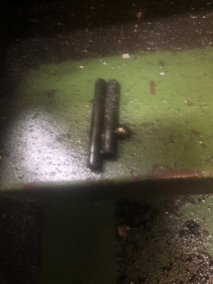
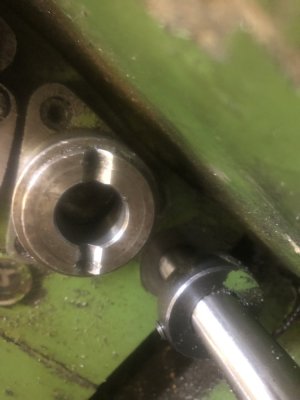
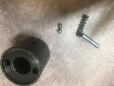
I think I found another issue on the feed rod though. I "think" that the feed collar which has two set screws, two ball bearings, one spring and one roll pin(in place of spring?) should really have two springs. This would allow it to disengage when it hits an endstop.
 

Attachments

  • IMG_0168.jpg
    IMG_0168.jpg
    57.9 KB · Views: 7
  • IMG_0169.jpg
    IMG_0169.jpg
    60.9 KB · Views: 6
  • IMG_0170.jpg
    IMG_0170.jpg
    77.7 KB · Views: 8
  • IMG_0171.jpg
    IMG_0171.jpg
    67.7 KB · Views: 9
  • IMG_0172.jpg
    IMG_0172.jpg
    71.1 KB · Views: 8
  • IMG_0173.jpg
    IMG_0173.jpg
    58.9 KB · Views: 9
  • IMG_0174.jpg
    IMG_0174.jpg
    63.5 KB · Views: 9
  • IMG_0175.jpg
    IMG_0175.jpg
    62.3 KB · Views: 8
  • IMG_0176.jpg
    IMG_0176.jpg
    79.1 KB · Views: 9
  • IMG_0177.jpg
    IMG_0177.jpg
    65.4 KB · Views: 9
  • IMG_0178.jpg
    IMG_0178.jpg
    103 KB · Views: 11
Your lathe looks generically like mine so I'll describe mine but there still could be differences. And I realized I didn't upload the pic I thought I did so attaching.

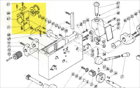
The clamshell action is controlled by the lever which turns a part with 2 pins (part 62 in my case). The drive pins slide inside the slots of the mechanism. When it turns it retracts the clamshell jaws up & down. Yes, the gib could require adjusted for tension, but that really doesnt affect the throw or centering. Its kind of pre-aligned in the assembly geometry. One thing to check is if the carriage body can be bolted at an angle or displaced in or out. This misalignment would then come down on the leadscrews off center & pull it back into itself (thus bowing the leadscrew). I noticed newer lathes have 4 top bolts to better self center, but mine only has 2. Better yet would be alignment dowels rather depend on the bolts to serve this duty.

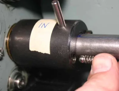
Your last pic is the clutch cup on power feed bar driveline I assume? It should have 2 bearing balls & springs & 2 set screws that capture them, one for hole. Basically if the rod sees excess torque or friction, the balls retract against the spring & come out of the V grooves they normally sit in to disengage transmitting rotation . When this happens you will hear this clackety-clack, its very noticeable. But this is a power feed mode issue only. Power feed is disengaged completely when you are in threading mode with clamshells engaged. There is a spring lever mechanism that locks out the power feed while in threading mode.

Dumb question, but when you are threading, you are engaging a knob on the front panel from power feed to threading mode, right?
 

Attachments

  • 2018-07-09_18-45-53.jpg
    2018-07-09_18-45-53.jpg
    58.4 KB · Views: 6
  • IMG_6414_edited-1.jpg
    IMG_6414_edited-1.jpg
    57.3 KB · Views: 6
  • IMG_6415_edited-1.webp
    IMG_6415_edited-1.webp
    33.4 KB · Views: 5
My roll pin goes through the clutch cup & power feed bar. Basically that is the hard connection right through the apron gears & obviously is what needs to be removed in order to slip the rod out through the carriage. The clutch mechanism (balls, springs, adjustment screws & V-groove in opposing shaft) is collectively the load sensitive 'disconnect' to the head stock shaft/drive gears.

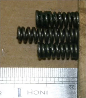
These show my old (squashed) vs new springs. But it may not necessarily be the same as yours. But just to give you an idea.
 

Attachments

  • new vs old springs.webp
    new vs old springs.webp
    23.4 KB · Views: 4
  • IMG_6384_edited-1.webp
    IMG_6384_edited-1.webp
    18.2 KB · Views: 4
not sure what the hell thread i'm cutting here, but it's cutting threads. Still seeing that slop which I believe might be in the gear train. I'm not seeing anything in the threads themselves as you can see.
Got ahold of Preston from Modern Tool. he's going to approach there suppliers about change gear sets for this lathe. And possibly a manual.

 
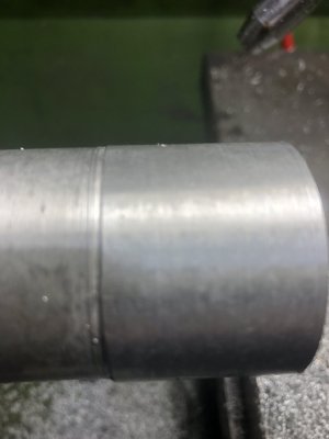
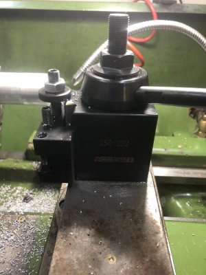
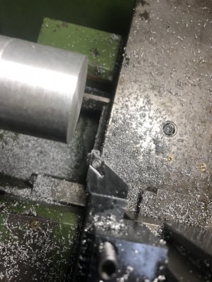
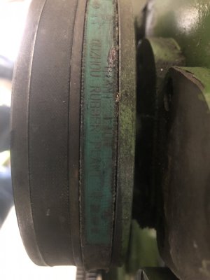
Just finished replacing headstock and gear change oil. replaced the oil I had used in the apron as well. Cleaned up ALOT of crap from everywhere. Need to find a source of either thick rubber or felt to use for the wiper's on the ways since the rubber is kinda screwed from age. Found out I have a 30 tooth, 60 tooth and the 127/120 tooth threading gears. This means I can do imperial threading except a couple of large sizes. I need to get 2 50tooth, a 40 and a 45tooth to be able to do metric threading and the oddball imperial. Still need to replace the belts though. They are the original belts and are kinda ratty looking. I believe they might have been rubbing against the stand since the edge on one is rather frayed. While I had the covers off, I moved the pulley on the motor over by about 1/8" and I think that might help the situation. Replaced the old style toolpost with a Accusize BXA wedge type quick change. Definitely need to get a few more holders and a 1inch boring bar. Thought I'd show my results from a quick turn attempt on some crap aluminum.

Anyone have any suggestions for a boring bar? has to have a 1in shank size.
IMG_0343.jpg
 

Attachments

  • IMG_0344.jpg
    IMG_0344.jpg
    48.7 KB · Views: 7
  • IMG_0345.jpg
    IMG_0345.jpg
    102.2 KB · Views: 7
  • IMG_0346.jpg
    IMG_0346.jpg
    140.2 KB · Views: 8
  • IMG_0347.jpg
    IMG_0347.jpg
    80.7 KB · Views: 9
  • IMG_0348.jpg
    IMG_0348.jpg
    106.4 KB · Views: 9
Good boring bars are very expensive. I find i can easily get away with using very cheap OD turning tools but ID turning tools are prone to vibration and deflection due to there long stick out. The good boring bars i have are iscar and kennametal. The only cheap one that i still use is my glanze bar from busy bee. I cut mine shorter because it only works about 2 inches deep in steel. It is not great but it is cheap.
 
Back
Top