• Scam Alert. Members are reminded to NOT send money to buy anything. Don't buy things remote and have it shipped - go get it yourself, pay in person, and take your equipment with you. Scammers have burned people on this forum. Urgency, secrecy, excuses, selling for friend, newish members, FUD, are RED FLAGS. A video conference call is not adequate assurance. Face to face interactions are required. Please report suspicions to the forum admins. Stay Safe - anyone can get scammed.

Mini Crane

thestelster

Ultra Member
Premium Member
I've been breaking my back for years lifting the 14" 4-jaw chuck from a dolly on the ground up to the bed of the lathe (protected by a thick piece of plywood of course), but doable.

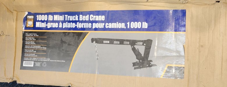
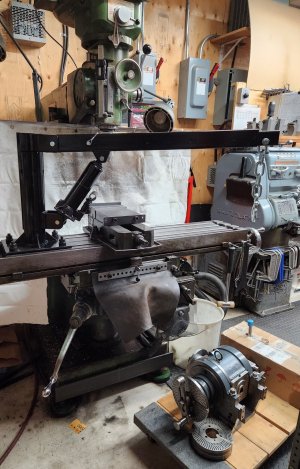
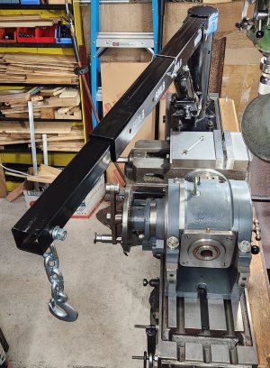
But now that I have my dividing head which weighs 138lbs, I need something to get it from the ground onto the table. Gantry, engine lift, overhead hoist were all a no-go for various reasons. But I found this at Princess Auto, on sale for $129.99. I will probably need a small hoist to attach to it though.
 

Attachments

  • 20230607_152422.jpg
    20230607_152422.jpg
    222.1 KB · Views: 22
  • 20230607_194315.jpg
    20230607_194315.jpg
    486.6 KB · Views: 23
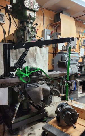
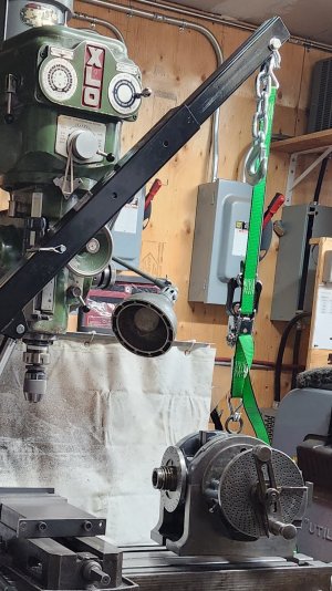
Ok, please, please, critique this set up for safety. It works well enogh

I do plan on removing the chain and hook on the boom and substituting with shackles. The tie-down is working load is rated to 1,000lbs. The dividing head weighs 138lbs. I had to extend the boom to the 700lb mark.
 

Attachments

  • 20230608_090525.jpg
    20230608_090525.jpg
    449.5 KB · Views: 17
  • 20230608_091709.jpg
    20230608_091709.jpg
    370.6 KB · Views: 16
Is there a risk of tipping the mill if the boom is extended with a load out front?
If so, maybe having the table snugged up to the column would help to move the COG further back.
 
Well, the mill weighs 2,900lbs, and I had the table to it's lowest position. I did have the table out, for clearance, but I'll see how far back I can put it. Thank you for your feedback.
 
Ok, you asked.......

The trouble is that you are lifting heavy things with that.

I'd be terrified of pulling a T-slot out when that thing is off to a heavy angle with a heavy load. The leverage is significant at right angles to the bed.

Also echo @Doggggboy's concern above.

In general, I wouldn't mount it on the bed. I'd mount it on the cart. That way it can stay there instead of having to install and uninstall it each time it's needed.

Yes, then you have the risk of an unstable cart. But you can always lift the tool above the cart and then slide the cart under the table so the cart is never unbalanced. Using a cart would make the lift useful for other things too.
 
I'd be terrified of pulling a T-slot out when that thing is off to a heavy angle with a heavy load. The leverage is significant at right angles to the b

Yeah there is a lot of leverage. Some years ago I bought a Sky Hook, absolutely obscenely price for what they are and it looks like they've double since then, but I wanted to save the back and get on with it quickly. Avoid piling more on project list and end up with a crane in 8 years instead of now as we're unlikley to get stornger as we age and you only get one shot at an undamaged back

For the T slot concern, I made a 6 inch long T slot nut. It greatly strengthened things, a much larger area would have to shear with the longer nut
 
Be very careful with the assumption that over centering wont happen with that outfit...I would probably use it the same as you do but would be nervous a s a cat with a tail at a roller derby.
Over centering crashes very seldom give a person time to remedy the situation...the teetertottering often just involves the teeter part LOL . You have to remember that although the mill weighs in at 2900 lbs, you only get the benefit of about a 1/3 of that weight left of center. And to add to that, although your dividing head only weighs in at 138, that is 138 at the center pivot of your hoist, out at the end of the jib there is a cantilever quotient that multiplies that amount of torque at the mill center.
There are no doubt math wizards on this forum that could figure out the actual torque on that mill center but I aint one of them so I'm with you on using that combination as photo'd but I'm still the nervous cat.
 
I'd be terrified of pulling a T-slot out when that thing is off to a heavy angle with a heavy load. The leverage is significant at right angles to the bed.
I agree. But the angle is only 20°. Maybe someone can do the math to determine what the forces are. The length of the boom to the center of the post is 41".

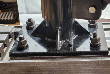
The bolts attaching to the t-slots are 1/2"-13 Teco, and miraculously the holes in the mouting plate are exactly the spacing of the tables t-slots. I only used 4 bolts, but the plate has provisions for 8 in total.

And I was thinking about a cart, but how heavy does the cart have to be to prevent it from tipping?
 

Attachments

  • 20230608_100514.jpg
    20230608_100514.jpg
    574.8 KB · Views: 7
  • 20230608_100620.jpg
    20230608_100620.jpg
    369.4 KB · Views: 6
As above, tipping maybe a problem, what might be a bigger problem is the table coming off the mill. Please note I have not looked at the specs for the mill. What is the table rated load? This load is most all a down force, leave out machining forces for now. Putting the boom out at 90 degrees to the table length, maybe 6ft. of boom length, times 138lb. of load, (which may become more, more cause it did that just fine) 850+- ft.lb of torque, held by one dove tail, the other would be just a pivot point. This is if the tee slots will not fail and tear out of the table.
I maybe over reacting, how ever that looks like a very fine mill. Is the mill fastened into the floor or just on damper pads? Cast iron is very good in compression, not very good in tension.
The mill might be built like a cast iron battle ship, look for the weak points that can sink it. LOL.
Can the hoist be mounted to the wall between the mill and lathe to serve both, lifting chucks, vises, dividing heads and "large barrels" LOL. etc.
I checked the manual, it doesn't state the max work weight, but i read Bridgeports are rated st 750 lbs, and the Excello 602 is a beefier mill.

The angle of the boom relative yo the table is 20%, and boom length is 41".

I have the mill on damper pads.

My shop is in the garage, so 2x6 studs and 3/4" plwood walls. The roof is typical trusses with sheet rock ceiling.
 
I'm worried about tipping issue to some extent, but far more so about breaking out a section of t-slot from the leverage exerted on the base. I've seen so many broken t-slots on mills and yes it is usually from using too long a bolt it is also due to the nature of cast iron.

It has been a long time since I calculated angular forces, but I know when I used to climb regularly and calculated angular forces but I do recall very well that the forces were always higher than I wanted.

I have been thinking of how I will be lifting things in the shop now that I can barely lift 5 pounds off the floor, and I had considered this same lift, but discarded the idea in favour of a boom arm that can offset some of the forces exerted on the extended boom. I was going to copy how the firefighting boom was mounted on the wm lyon mackenzie tugboat.

Below you can see that the fulcrum is outbound of the base, and that the piston would be exerting downward pressure more in line with the center of the base rather than trying to lever the base off of the mill table.

1686241206151.webp


In your case, I'd do as @Susquatch suggests and install the crane on a cart with a weighted base and a steel top. Much stronger arrangement... additional benefit of being mobile and therefore more useful.
 
Since I was asked... The lever arm of 41" versus the centre holes to edge of plate, say 4" is a 10:1 lever in the T bolts/T Nuts... making about 1000 lbs torque... While the cast iron can handle this unless there is a flaw in the casting,, I have a suggestion or 2.

1. Consider adding 2 holes to the plate and add 2 more t nuts/bolts, This will halve the strain on the bolts/casting

2. Consider shortening your arm as much as practical - skyhooks and Mr Pete's crane used arms around 24". This will further reduce the strain on the table, and making 'gong down' a little slower.

3. I wouldn't worry too much about tipping a full sized mill. It would take more than the weight of the mill to tip it forward at 41" On an angle, about half the weight of the machine. To the side (at 90 degrees) about 1/4 the weight of the machine.
 
I agree. But the angle is only 20°. Maybe someone can do the math to determine what the forces are. The length of the boom to the center of the post is 41".

Might as well say 4 ft acting on a 4 inch bolt span. 138pounds might as well say 150 to be conservative since there are chains and hooks In other words and other oversights (I always round up to keep the math simple and add some safety factor). So 150 x 4 x 3 = 1800 pounds trying to twist your bed.

@Mcgyver is right about longer nuts but they have to be high strength steel or they simply bend and leave the load focussed. Cast iron doesn't bend, it just breaks. So the load still gets focussed - albeit not nearly so badly. Everything you do to distribute the load helps but not often as much as expected.

Odd unexpected things happen when you have multiple fasteners. You have to do a force diagram. But basically, the leverage introduced by the close fasteners increases the load on the far fasteners. Think of it a bit like a pry bar.

Your bed may be rated for 750 or even 1000 pounds, but that is straight down, not twisting. I don't like twisting.

The bolts attaching to the t-slots are 1/2"-13 Teco, and miraculously the holes in the mouting plate are exactly the spacing of the tables t-slots. I only used 4 bolts, but the plate has provisions for 8 in total.

The number of bolts, their size, and their strength is important in tension loads, but doesn't really improve this situation much. Might even "zipper" to use a term someone else mentioned earlier in another thread. (Obviously I liked it!) Your weak point is the cast iron lips in the T-Slots, not the fasteners.

And I was thinking about a cart, but how heavy does the cart have to be to prevent it from tipping?

If the load is lifted straight up off the cart and then, the cart is pushed under the table the way I described earlier, the cart could be a feather. It's a much better scenario than mounting the lift on the bed.

Obviously, a strong heavy cart would be better that a feather. I just used that to point out that weight isn't a big factor if the load is lifted up and not hung out over the side. Also a steel cart has give - it's not like cast iron.

I'd make a nice heavy steel cart, with wide stance easy roll wheels, and mount your mini-crane to that permanently. You could even add foldable stabilizer legs, etc.
 
Back
Top